Match the Transfer Scheme to the Building’s Loads
An automatic transfer switch (ATS) moves selected loads between normal and alternate power sources when the normal source is unacceptable, then coordinates a return when conditions permit. For a commercial building, the first decision is not simply switch amperage; it is which loads must transfer, how quickly they need restoration, and whether they can tolerate a brief interruption. Life-safety, legally required standby, critical operations, and optional standby loads may have different design and code obligations. Engineers should identify the intended source arrangement, load priorities, transfer sequence, and any requirements for open-transition or closed-transition operation. These choices affect switch configuration, controls, coordination, and upstream equipment. Confirm the applicable codes and authority requirements for the project rather than assuming one transfer scheme suits every building or occupancy.
Define Electrical Ratings and Source Conditions
Procurement documents should describe both sources, not just the normal service. Specify system voltage, phase, frequency, ampacity, available fault current, neutral arrangement, and grounding details where established by the design. The ATS must be evaluated for the system conditions and protective-device coordination; a switch rating alone does not confirm suitability for the installation. Identify whether the alternate source is a generator, a second utility source, or another approved supply, and document its characteristics and operating limits. Generator starting, voltage and frequency recovery, and load sequencing can influence transfer delays and control settings. Include the intended enclosure location and environmental conditions, such as indoor electrical-room placement or exposure to moisture, dust, or temperature variation. Final ratings and compatibility remain project-specific and should be confirmed against drawings and equipment data.


Coordinate Controls, Sensing, and Generator Operation
The control package determines how the ATS recognizes source failure and manages transfer, so its interfaces deserve early review. Clarify which voltage and frequency conditions initiate transfer, how restoration is recognized, and whether programmed delays are needed to avoid responding to momentary disturbances. Coordinate those decisions with the generator controller, building automation system, fire alarm interfaces, and any remote annunciation specified by the engineer. Confirm what signals must be exchanged, which party supplies wiring, and where terminal schedules will be shown. Exercise and test provisions should align with the owner’s operating plan and applicable project requirements. Do not assume a standard control arrangement will work with every generator or monitoring platform. A points list, sequence of operation, and control schematics help expose gaps before fabrication, commissioning, or site installation.
Plan Installation Around Room and Service Constraints
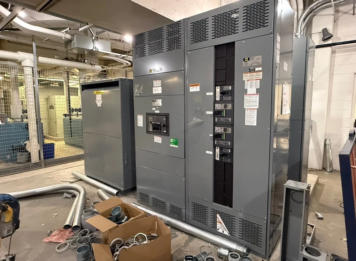
An ATS replacement or new installation has to fit the electrical room as well as the one-line diagram. Check access routes, door openings, overhead clearance, working space, cable entry direction, conduit locations, and the space needed to service the installed equipment. Existing buildings can impose restrictions that are absent from new construction drawings, including limited shutdown windows, congested distribution rooms, or feeder conductors that cannot be readily rerouted. Record field dimensions and verify the intended mounting and termination arrangement before approving submittals. The installation plan should also identify which loads are interrupted during connection and testing, and how required temporary power or outage notices will be handled by the project team. All electrical work must follow applicable safety procedures, including establishing an electrically safe work condition where required; energized work is not a substitute for sound planning.
Prepare Submittals for Review and Procurement
A complete request for quotation gives the manufacturer a practical basis to develop a new ATS assembly for the project. Provide the one-line diagram, equipment schedule, source and load information, fault-current data, sequence of operation, enclosure requirements, connection details, and any specified standards or listing requirements. Identify whether the equipment is new construction or replacement work, and include relevant existing-equipment information when available. Ask for drawings and documentation needed by the design team, such as dimensional layouts, wiring diagrams, terminal information, and product data for review. Requirements for UL 891 apply to appropriately evaluated low-voltage switchboard assemblies; they are not a blanket certification for all transfer switches or for medium- and high-voltage equipment. Confirm the exact product evaluation and project requirements rather than treating a general standard reference as proof of a particular label.
Align Build Timing, Delivery, and Site Readiness
Schedule coordination starts with a complete, approved scope. Custom configurations, component selection, drawing review, approval cycles, and changes to source or control requirements can all affect the manufacturing sequence. Discuss expected timing with the U.S. manufacturer during quotation, and confirm the schedule against the specific design, material availability, approvals, and shipping plan; short lead times may be offered, but no duration should be assumed without project confirmation. Nationwide shipping can support projects across the country, yet receiving conditions still need attention. Confirm the delivery address, unloading equipment, access hours, indoor storage, weather protection, and who will inspect and accept the shipment. Tie delivery to room readiness, construction progress, outage planning, and the commissioning team’s availability. Resolve open submittal comments before release so late revisions do not create avoidable coordination or installation problems.