Engineering Begins With the Distribution Requirements
A switchgear package should be engineered from the electrical system it must serve, not from a catalog description alone. Start with the one-line diagram, service voltage, available fault current, system grounding, source configuration, and the loads that must remain available during maintenance. These details affect bus arrangement, protective-device selection, compartment layout, and provisions for future circuits. For a replacement, gather existing nameplate data, connection dimensions, cable entry locations, and control schematics; equipment that fits the room may still be incompatible with the installed system. Procurement teams can reduce bid gaps by identifying the governing project specifications, applicable standards, and required submittals before requesting pricing. Final ratings, construction, and standards compliance depend on project-specific engineering review.
Busbar Fabrication and Connection Planning
Busbar design links electrical capacity to the physical arrangement of the assembly. Material, cross-section, bracing, joint locations, and clearances must be considered together with the specified current and fault conditions. A bus configuration that looks compact on paper can complicate field connections if it conflicts with cable bend space, conduit positions, or the way the equipment enters the room. Provide the manufacturer with available room dimensions, access routes, termination details, and any limits on overhead or rear access. Joint locations also matter for installation sequencing and future inspection. American components are available, but component selection and compatibility should be confirmed against the project documents rather than assumed from origin alone. Bus details and ratings remain subject to design review.


Enclosure Layout for the Actual Site
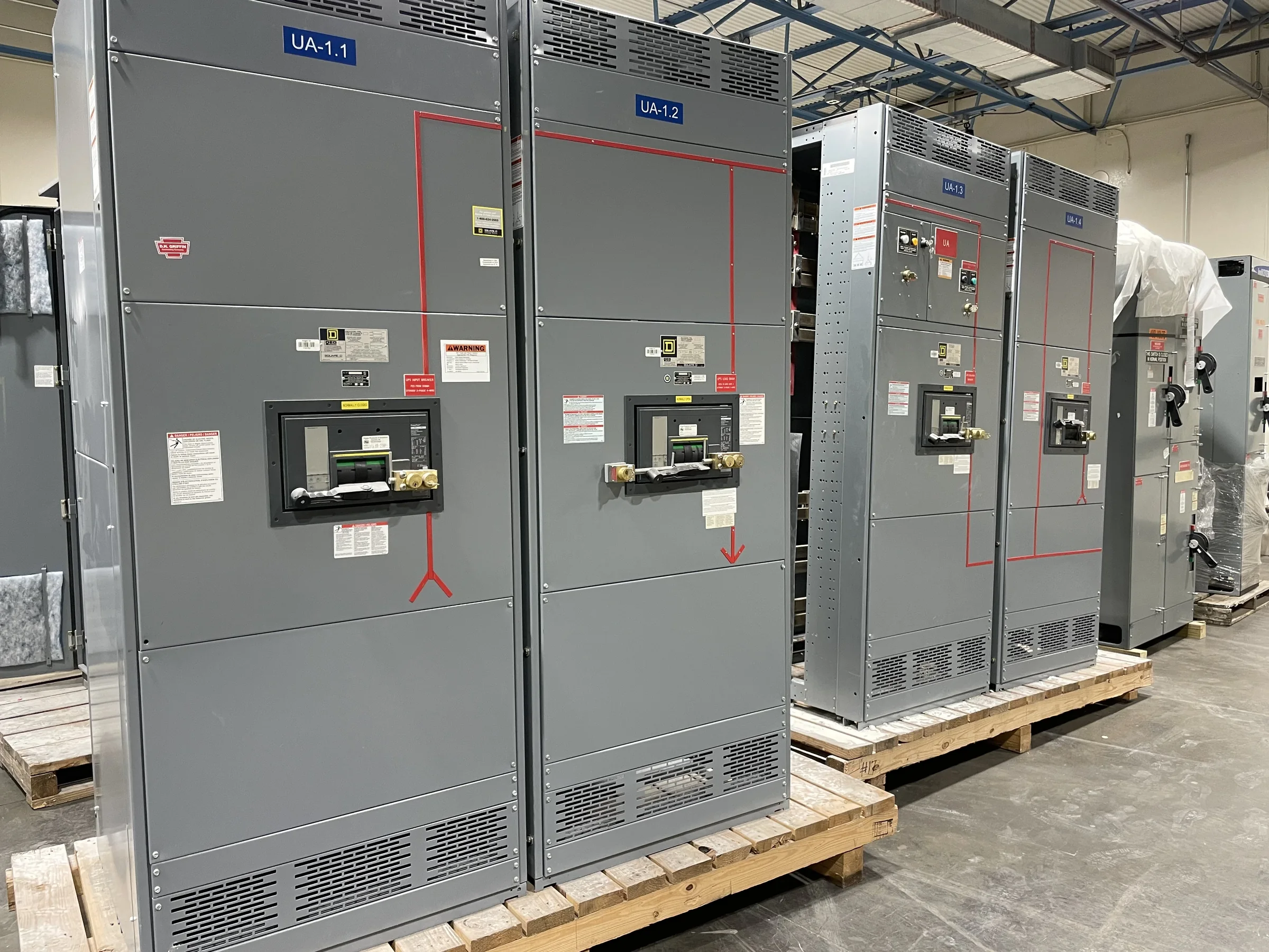
The switchgear lineup has to work within the electrical room, loading path, and maintenance plan—not just within its drawing boundary. Door swing, aisle clearance, wall obstructions, floor openings, ceiling height, and removal space can affect section arrangement and service access. Confirm whether conductors enter from above, below, or the side, and identify where building structure or existing services limit routing. For retrofit projects, measure the path from the unloading point to the final position; a lineup that cannot pass a doorway or turn in a corridor may require a different shipping split or installation sequence. Share verified site dimensions and photographs with the quote request, while treating field measurements as subject to confirmation. Final layout depends on equipment and site review.
Assembly, Components, and Build Coordination
Assembly decisions bring electrical requirements, mechanical construction, and procurement timing into one coordinated package. The approved bill of materials should identify devices, metering, controls, and accessories by function and interface, while drawings show how those items connect to the incoming source and outgoing circuits. Substitutions can affect dimensions, wiring, protection coordination, or compatibility with existing control systems, so review proposed changes before release to production. If the project requires American components, state that preference in the inquiry and identify any specified manufacturers or approved-equal rules. Custom builds and short lead times are offered, but timing depends on scope, component availability, drawing approvals, and production scheduling. Agree on review responsibilities and required dates early to avoid preventable holds.

Testing and Documentation Before Shipment
Factory testing and project records help confirm that the assembled equipment matches the approved design before it reaches the jobsite. Define required inspections, electrical checks, witness points, and test documentation in the procurement specification; the exact scope depends on the equipment and contract requirements. Ask how drawing revisions, device settings, terminal schedules, and wiring diagrams will be controlled so the installation team receives consistent information. UL 891 applies to appropriately evaluated low-voltage switchboard assemblies, not as a blanket designation for medium- or high-voltage equipment; confirm the applicable evaluation and labeling requirements for the specific assembly. A clear submittal list also helps the engineer review dimensions, ratings, and interfaces before fabrication. Testing scope, records, and compliance are project-specific.
Delivery Planning, Installation, and Replacement Work
Shipping coordination starts with the receiving site, not when the equipment leaves the factory. Identify the delivery contact, unloading capability, indoor storage conditions, access restrictions, and any limits on truck size or delivery hours. Nationwide shipping is available, but route, packaging, shipment configuration, and timing must be coordinated for each order; do not assume a delivery date until it is confirmed in the project schedule. For replacement work, plan outages, temporary power needs, removal access, and the sequence for reconnecting feeders and controls with the responsible electrical professionals. Work on electrical equipment must follow applicable safety procedures, including de-energization where required. Provide the manufacturer with schedule milestones and site constraints when requesting a quote so the proposed build can be evaluated against installation realities.