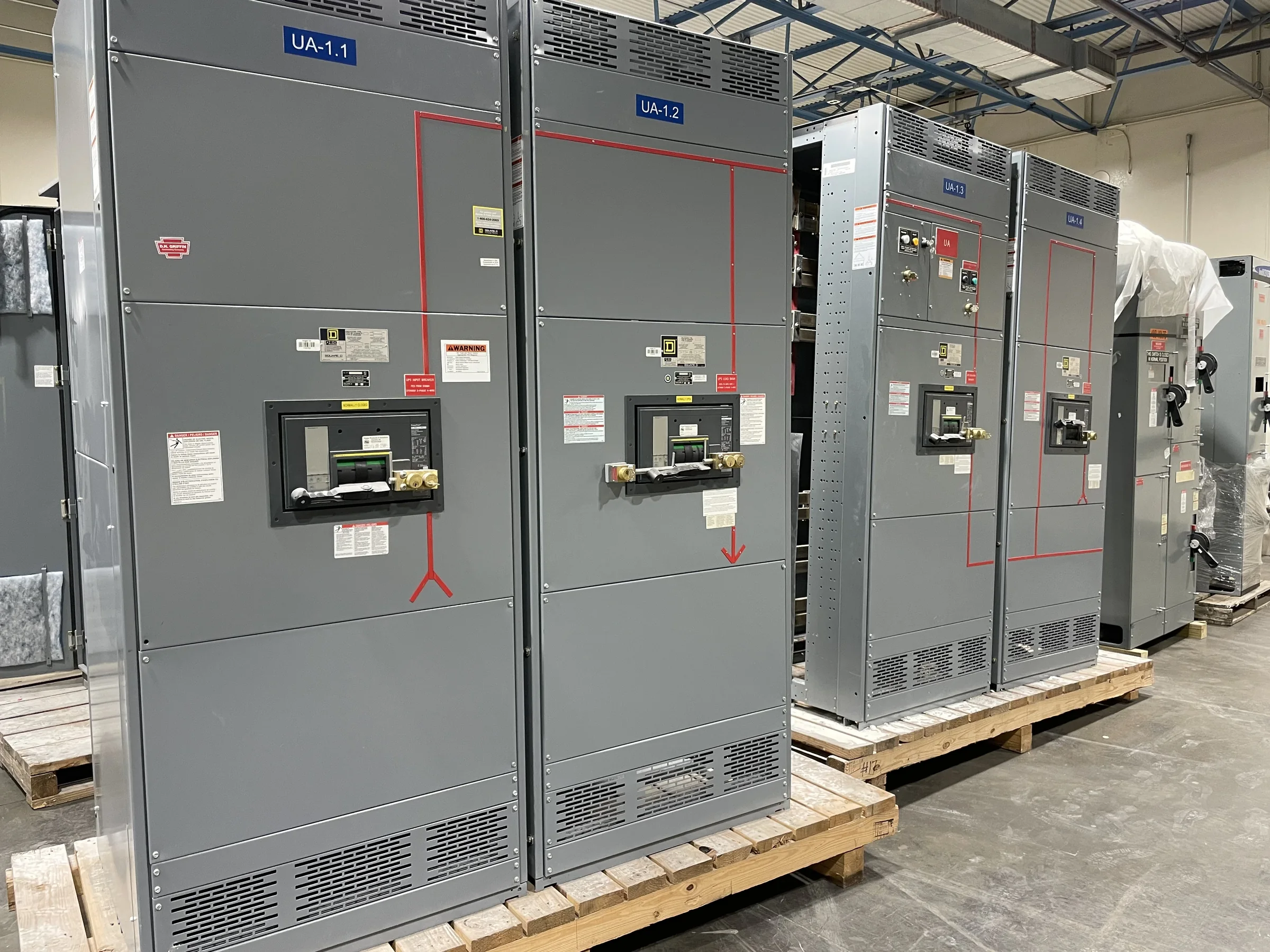
Separate Essential Loads by Process Consequence
In a petrochemical facility, an automatic transfer switch (ATS) should be selected around the consequence of losing each served load, not simply its nameplate size. A control-room UPS, instrument-air compressor, fire pump, cooling-water pump, and general utility panel may have different continuity requirements and may not belong on one transfer scheme. Process engineers and electrical designers should identify which loads must remain available, which can tolerate an interruption, and which require an orderly shutdown. That distinction affects source arrangement, switch construction, controls, and coordination with generators or alternate utility feeds. A clear load schedule also prevents avoidable oversizing or a design that transfers nonessential demand onto limited emergency capacity. Final ratings and applicability depend on documented system conditions and engineering review.
Define Sources, Transfer Logic, and Return Behavior
Specify the normal and alternate sources, their grounding arrangements, and the intended transfer sequence before requesting an ATS quote. Petrochemical systems may include utility service, standby generation, or separately supplied buses; the design must account for source voltage and frequency limits, available fault current, neutral treatment, and protective-device coordination. Decide whether transfer is open transition, closed transition, or another approved arrangement based on the process and utility requirements. Also document how the switch should respond to a failed source, an unavailable generator, and restoration of normal power. Return-to-normal timing and any required manual control deserve particular attention: an abrupt retransfer can disturb motors, instrumentation, or process controls. The applicable sequence, ratings, and compatibility must be confirmed for the specific project.


Account for Corrosive, Hot, and Dusty Areas
Installation conditions can change equipment selection and enclosure requirements. Petrochemical sites may have salt-laden air, chemical vapors, conductive dust, high ambient temperatures, vibration, or washdown exposure, depending on the unit’s location. Identify the actual environment and indoor or outdoor mounting arrangement rather than relying on a broad facility description. The electrical area classification is especially important: an ATS intended for an ordinary electrical room is not automatically suitable for installation in a classified location. Provide the project’s classification documents, environmental criteria, enclosure requirements, and any applicable site standards for review. These details affect design, placement, access, and installation interfaces; overlooking them can lead to rework or an unsuitable assembly. Final suitability must be established by the project team and equipment documentation.
Coordinate the ATS With Protection and Controls
Transfer equipment sits between power sources and process loads, so its interface with upstream protection and downstream distribution should be reviewed as one system. Provide available fault-current information, one-line diagrams, protective-device settings or coordination criteria, and connected-load data when developing the specification. Motor starting, transformer inrush, and nonlinear loads can influence sensing and transfer behavior; they should not be reduced to a simple total-kilovolt-ampere figure. Document required control contacts, alarms, status points, remote interfaces, and any communications protocol so the ATS can be integrated with the facility’s control scheme. Confirm who supplies wiring, control power, and field connections at each interface. These checks help prevent nuisance transfers, incompatible signals, and gaps between equipment responsibilities. Final coordination and performance remain project-specific.
Prepare a Complete RFQ and Submittal Package
A focused request for quotation helps the manufacturer evaluate the application without guessing at critical conditions. Include the one-line diagram, load schedule, source characteristics, system voltage, phase and frequency, fault-current data, transfer sequence, environmental requirements, installation location, and requested standards or documentation. Identify whether the scope includes a new assembly, replacement, or retrofit, and provide existing-equipment information where relevant. For a retrofit, dimensions, cable-entry directions, connection details, and site photographs can expose physical constraints early; compatibility should never be assumed from a similar model name. Ask the supplier to identify exceptions, required customer decisions, and submittal documents for review. Ratings, construction, standards, availability, and any evaluation or labeling are confirmed against the actual scope, not inferred from a general product description.
Plan Delivery Around Site Access and Commissioning
On a petrochemical project, delivery is only useful when the equipment can reach its final location and be installed within the site’s work controls. Confirm receiving hours, security and badging requirements, unloading responsibility, route dimensions, doorway and laydown limits, lifting provisions, and whether phased shipment is acceptable. Coordinate the requested delivery window with outage planning, contractor mobilization, and any required inspection or document approvals; do not treat a preliminary schedule as a guaranteed ship date. Before energization, qualified personnel should verify installation, grounding, control wiring, protection settings, and the approved transfer sequence under the facility’s safety procedures. A manufacturer can discuss custom-build requirements, American components, and nationwide shipping during procurement, while actual configuration and timing depend on the project review. Written scope alignment reduces late changes and site delays.