Define the Transfer Duty Before Selecting Equipment
At a power plant, an automatic transfer switch is part of a defined operating scheme, not a stand-alone way to move a load between two sources. Begin with the loads it serves, the normal and alternate sources, and the conditions that should initiate transfer or retransfer. Identify whether the switch serves station auxiliaries, control power, building services, or another defined load group; these duties have different consequences if power is interrupted. The design team should establish acceptable transfer behavior, source availability signals, and any required time delays in coordination with plant controls and protection. These decisions matter because a switch that meets a broad description may still conflict with the plant’s operating sequence. Final ratings, functions, and application suitability depend on the project review.
Coordinate Source Behavior and Protection
Two available sources are not necessarily interchangeable. A generator-backed bus, utility service, and plant bus can differ in voltage, frequency behavior, grounding, fault contribution, and protection settings. The transfer scheme should therefore be reviewed alongside source and load characteristics, upstream and downstream protective devices, and the plant’s control logic. Clarify whether transfer is open-transition or another specified method, and whether synchronism or an intentional interruption affects the application. A mismatch can produce nuisance transfers, excessive interruption, or coordination problems that disrupt essential auxiliaries. Provide one-line diagrams, control narratives, and relevant protection information with the equipment inquiry so the proposed arrangement can be evaluated. Specific compatibility and performance are project-dependent; do not assume a standard switch configuration resolves every source interaction.


Account for Plant Loads and Operating Priorities
Power plants often serve loads with markedly different consequences of interruption. Instrumentation, lubrication, cooling, ventilation, battery chargers, and noncritical building loads may not belong in one undifferentiated transfer group. Confirm load type, starting or inrush characteristics, operating sequence, and whether simultaneous pickup is acceptable. Motor loads can make a seemingly adequate source arrangement perform poorly if the transfer sequence causes a large aggregate demand or voltage dip. The plant engineer should identify which loads require continuity, which can tolerate a pause, and whether load shedding or staged restoration is part of the approved scheme. These details help determine the appropriate switch arrangement and controls, but they do not replace system studies or site engineering. Submit actual load and sequence data rather than relying on nominal load descriptions.
Plan the Enclosure Around the Electrical Room
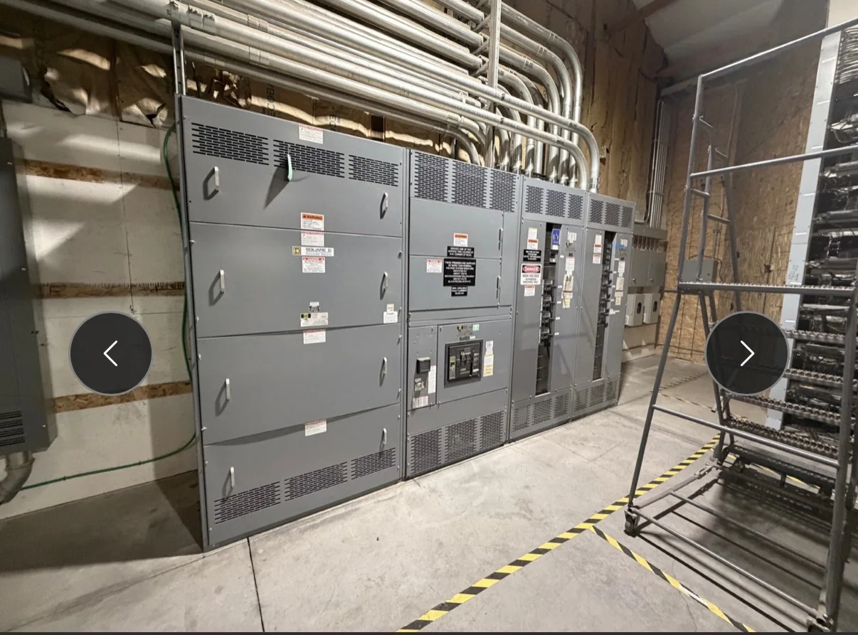
A suitable electrical rating is only part of a workable installation. Verify room access, equipment footprint, working clearances, cable entry direction, conduit locations, bend space, and the path from receiving area to final position. Existing plants may have narrow doors, overhead obstructions, congested cable trenches, or limited room for maintenance access; discovering these constraints after fabrication can force costly layout changes. Document environmental conditions such as ambient temperature, dust, moisture, corrosion exposure, and ventilation so enclosure and installation requirements can be reviewed. Identify whether the switch is intended for a new lineup or integration into existing distribution equipment, and provide available drawings and dimensions. Final construction and fit are specific to the approved design and site conditions, not inferred from a product name.
Make the Quote Package Useful for Engineering Review
A clear request for quotation helps the manufacturer evaluate the actual plant duty instead of pricing an incomplete description. Include the latest one-line diagram, source characteristics, load schedule, required operating sequence, control interface expectations, and applicable project specifications. Note the intended location in the plant, installation environment, cable and termination requirements, and any constraints imposed by existing equipment. Identify requested documentation, review milestones, inspection or testing expectations, and the responsible contacts for engineering questions. If the project involves replacement work, provide existing equipment nameplate information and interface drawings where available; matching an old description alone does not confirm electrical or physical compatibility. State which details remain preliminary. This record gives procurement and engineering a shared basis for clarifications, scope alignment, and a project-specific proposal.
Coordinate Build Timing, Shipping, and Site Readiness
For plant work, delivery timing must align with more than the purchase order. Confirm drawing review and approval responsibilities, required submittal dates, construction sequence, outage planning, receiving capacity, and the date the installation area will be ready. A short lead time may be available for some custom builds, but schedule and availability depend on the approved design, components, and project requirements; obtain current confirmation rather than assuming a delivery date. Nationwide shipping can support projects across the United States, while access restrictions, unloading equipment, indoor storage, and weather exposure still require site coordination. Assign responsibility for freight receipt and inspection, and keep the equipment protected until installation. Before turnover, verify approved drawings, field connections, control interfaces, and commissioning responsibilities with the project team; energization and testing must follow qualified personnel’s procedures.