Define the Utility Transfer Scheme Before Selecting Equipment
An automatic transfer switch (ATS) changes a load’s connection between normal and alternate power sources when the control scheme detects an acceptable transfer condition. For utility applications, the first decision is not simply switch size: establish whether the arrangement serves a utility facility, a customer installation at a utility interface, or a designated load within a larger distribution system. Document each source, the intended normal position, the loads transferred, and the operating sequence, including how the system responds when one source returns. Clarify whether the application requires open-transition, closed-transition, or another approved operating method; these approaches have different coordination and utility-interconnection implications. Source voltage, phase, frequency, available fault current, load characteristics, and the project’s governing requirements must be reviewed together. The selected arrangement is project-specific, not a universal utility configuration.
Coordinate Source Protection, Controls, and Interconnection Requirements
Transfer equipment must work with the protection and control philosophy on both sides of the switch. Gather the utility’s applicable interconnection requirements, source protection information, grounding arrangement, and any restrictions on paralleling before the design is finalized. Confirm how the ATS senses source availability, what conditions permit a transfer, and whether automatic retransfer is intended or requires operator authorization. Time delays can help prevent unnecessary switching during brief disturbances, but their settings must reflect the load, source behavior, and approved operating sequence; they should not be assumed from a generic template. Also identify how protective devices, upstream equipment, and downstream loads coordinate during abnormal conditions. These details matter because a switch can be mechanically suitable yet fail to meet the project’s operating or coordination needs. Final ratings, control logic, and utility acceptance require project-specific review.


Match the Assembly to the Load and Electrical Environment
Specify the load profile as carefully as the source characteristics. Motors, transformers, electronic loads, and other equipment can impose different starting currents or respond differently to a transfer, so provide load schedules and identify any loads that should be shed, sequenced, or excluded. Review the intended continuous load, system voltage, pole configuration, withstand and short-circuit requirements, and the protective-device arrangement with the responsible engineer. Environmental conditions also affect selection: indoor versus outdoor placement, ambient temperature, moisture, dust, corrosive exposure, vibration, and available working clearance should be stated in the inquiry. For utility facilities, the switch may sit in a constrained electrical room or a remote enclosure with limited access, making dimensions and service approach important. Do not infer a rating or enclosure suitability from product family alone; confirm each requirement for the specific assembly.
Provide Drawings and Records That Support a Buildable Scope
A complete request for quotation gives the manufacturer enough information to identify unresolved engineering decisions before fabrication begins. Useful documents include a one-line diagram, equipment schedules, load data, source and fault-current information, control narratives, site plans, and applicable utility or owner specifications. Identify required interfaces, conduit entry areas, cable or bus connections, communication points, and any restrictions on dimensions or access. State the applicable standards and whether a particular evaluation, labeling, or documentation requirement applies to the proposed equipment. UL 891 relates to appropriately evaluated low-voltage switchboard assemblies; it should not be treated as a blanket certification for medium- or high-voltage equipment or for every transfer-switch configuration. Mark assumptions and open items clearly. This reduces avoidable revisions, helps engineering assess compatibility, and gives procurement a clearer basis for comparing scope rather than comparing incomplete equipment descriptions.
Plan Schedule Around Engineering, Approvals, and Site Readiness
A requested ship date is only one part of the project schedule. Custom configurations may require drawing development, customer review, utility coordination, confirmation of interfaces, and resolution of technical questions before the assembly can proceed through the planned build sequence. Provide the required in-service date, approval milestones, site constraints, and any phased delivery needs when discussing timing with the manufacturer. Short lead times may be available for suitable scopes, but timing depends on the finalized design, component availability, approvals, and current production conditions; no delivery period should be assumed without project confirmation. Check whether the receiving site can accept the assembly when it ships, including unloading equipment, doorway and route clearances, storage conditions, and protection from weather or construction damage. Early coordination matters because a completed unit can still disrupt a project if the site is not ready to receive or install it.
Coordinate Delivery, Installation Planning, and Replacement Scope
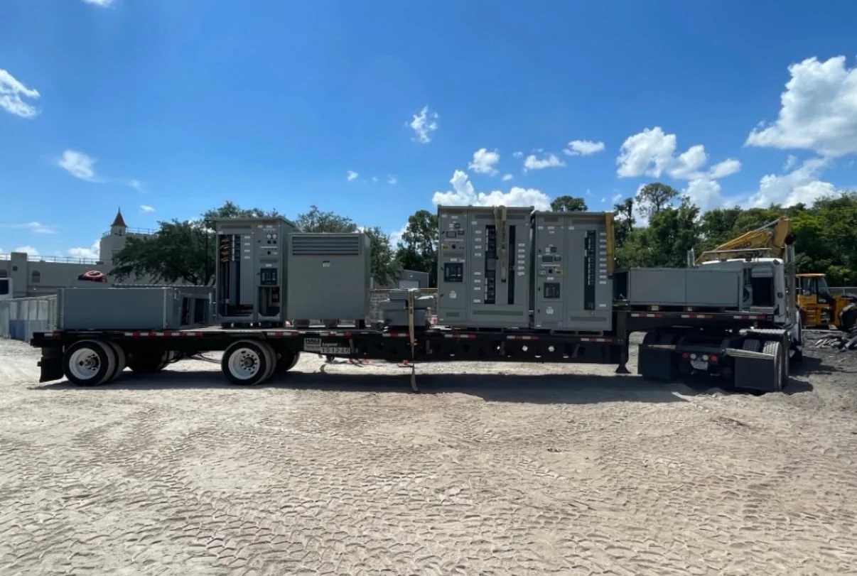
Nationwide shipping can support utility projects in different regions, but delivery planning should reflect the actual destination and site conditions. Confirm the ship-to location, receiving hours, access route, unloading responsibility, and any carrier or site restrictions before release. For replacement work, document the existing equipment’s nameplate data, dimensions, connection points, control wiring, and operating sequence; photographs and field-verified measurements can expose conflicts that a one-line diagram will not show. A proposed replacement or retrofit must be checked for electrical compatibility and physical fit rather than assumed to be a direct substitution. Installation planning should account for required outages, approved switching procedures, commissioning responsibilities, and coordination with the utility and facility stakeholders. Electrical work must be performed by qualified personnel under applicable safety procedures, with equipment properly de-energized when required. Confirm final scope and delivery details before placing the order.