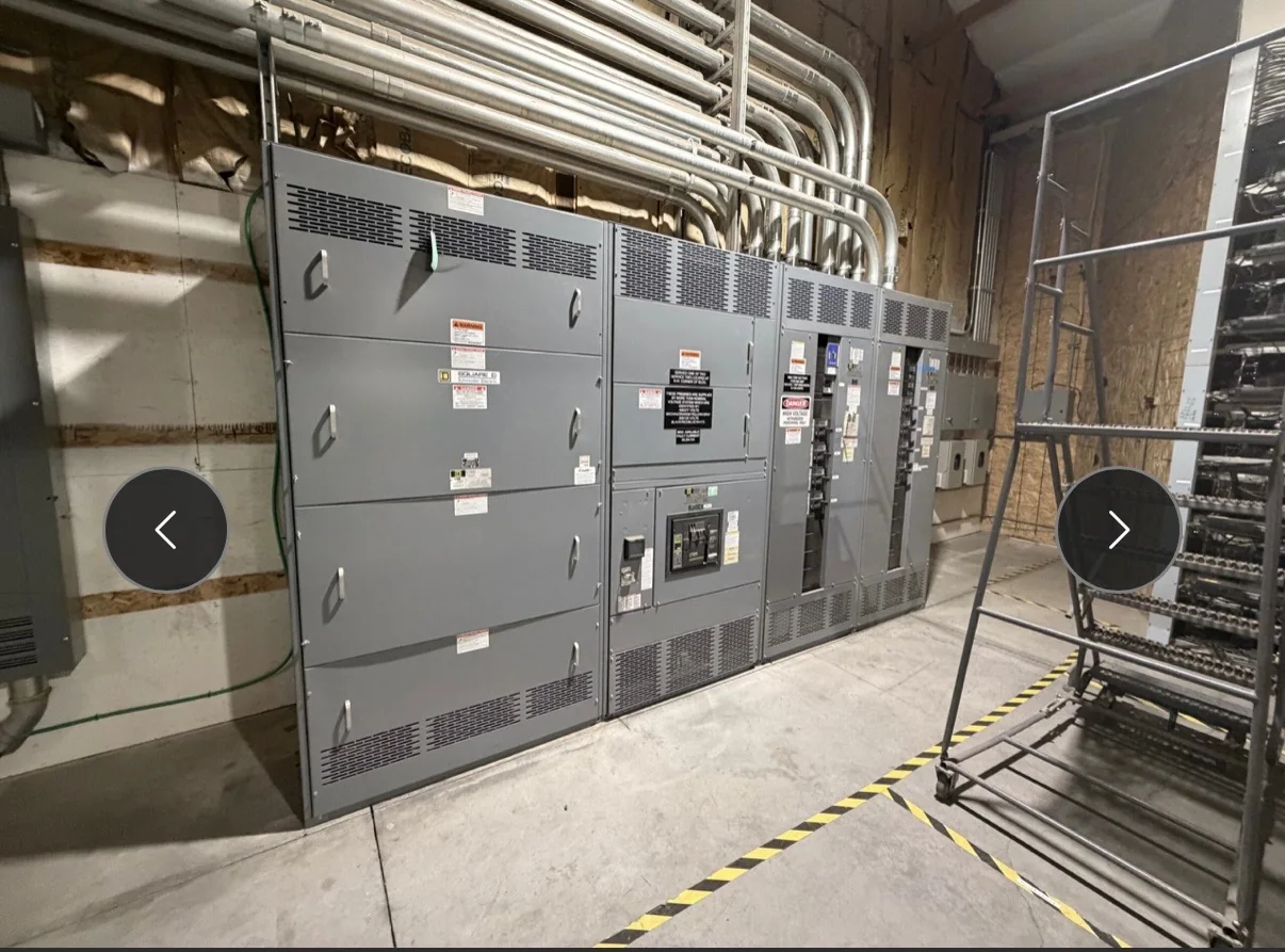
Translate Data-Center Loads Into a Clear Equipment Scope
A data-center switchgear package should begin with the electrical architecture, not a generic equipment list. Document utility service, generator sources, UPS outputs, bypass arrangements, and the loads each distribution section must serve. Identify whether the equipment is for service entrance, generator paralleling, critical distribution, or another duty; these functions can call for different construction and coordination. Capture voltage, phase, frequency, available fault current, continuous load, and required interrupting ratings as project inputs for engineering review, not assumptions. Redundant power paths also affect section arrangement and isolation needs. A one-line diagram that shows normal and alternate sources helps the manufacturer identify interfaces and open questions before fabrication, reducing the risk that a delivered assembly will not match the intended system.
Coordinate Protection, Selectivity, and Fault-Duty Requirements
Protection decisions shape both the electrical performance and physical lineup. Provide the latest available short-circuit study, protective-device settings, and coordination requirements, including any selective-coordination criteria that apply to critical branches. Confirm the utility contribution, transformer data, generator characteristics, and upstream device information used in those studies; changes in source configuration can alter fault duty and coordination. Ask the project engineer to resolve discrepancies between drawings and study documents before equipment release. Breaker frame and trip choices, bus ratings, and compartment requirements must be reviewed against the system design and applicable codes. This matters in a data center because an unintended trip can interrupt loads beyond the faulted circuit, while inadequate fault-duty selection can make the proposed assembly unsuitable for its point of installation.


Fit the Lineup to the Electrical Room and Service Route
Room dimensions are only part of the fit check. Submit plans showing lineup limits, clear working space, door swings, overhead obstructions, cable-tray approaches, conduit entry zones, floor openings, and the route from the receiving point to the final room. Note floor loading limits and any restrictions on lifting, turning, or temporary staging. Bus duct connections, bottom-entry feeders, and top-entry conductors require different coordination, so the equipment arrangement should be reviewed alongside the building model and electrical drawings. Data-center rooms may be built out in phases, making future extensions and reserved access important even where later equipment is not part of the initial order. Early dimensional review helps prevent field modifications, blocked maintenance access, and delivery-day surprises.
Specify Serviceability for Continuous Operations
Plan maintenance access around the operating strategy rather than assuming equipment can be shut down whenever service is needed. Identify which sections must be isolated independently, how alternate feeds are arranged, and whether the design calls for drawout devices, barriers, metering, or other features to support the approved maintenance plan. These choices depend on the one-line, applicable codes, and project risk criteria; no lineup feature alone guarantees uninterrupted service. Confirm control-power sources, interlocking requirements, monitoring interfaces, and points needed by the facility’s power-management system. Provide the intended device naming and alarm conventions early so drawings and labels can be coordinated. Clear service boundaries matter because operators need to understand what a switching action affects, while maintenance procedures must still require de-energization and verification before work.
Align Submittals, Interfaces, and Release Dates
A realistic schedule starts with complete inputs and named approval responsibilities. Establish dates for approved-for-construction drawings, utility or engineer review, protection-study updates, control-interface decisions, and release to production. Custom construction and short lead times may be available, but timing depends on the final scope, component availability, drawing approval, and project changes; confirm a schedule for the specific order rather than relying on a general estimate. Define who supplies relays, communications equipment, metering, or building-management-system requirements, and who verifies compatibility. Track open items in a decision log with owners and due dates. This discipline is especially valuable when switchgear must align with generator, UPS, transformer, and room-completion milestones, since a late interface decision can hold up testing or installation even when the assembly itself is ready.
Plan Delivery, Receiving, and Project Records
Nationwide shipping does not eliminate the need for a site-specific receiving plan. Coordinate shipment timing with gate access, unloading equipment, dock capacity, indoor storage, weather exposure, and the approved path to the electrical room. Confirm package dimensions and weights from project documentation before arranging rigging, and establish who will inspect the shipment and report damage or shortages. For phased data-center construction, identify the correct building, room, delivery window, and package sequence so equipment does not obstruct active work or remain in unsuitable storage. Request the applicable submittal drawings, wiring information, bills of material, and operation and maintenance documentation for review and turnover. UL 891 applies to appropriately evaluated low-voltage switchboard assemblies; verify the required evaluation and labeling for the specific equipment. Ratings, standards, and shipping details remain project-specific.