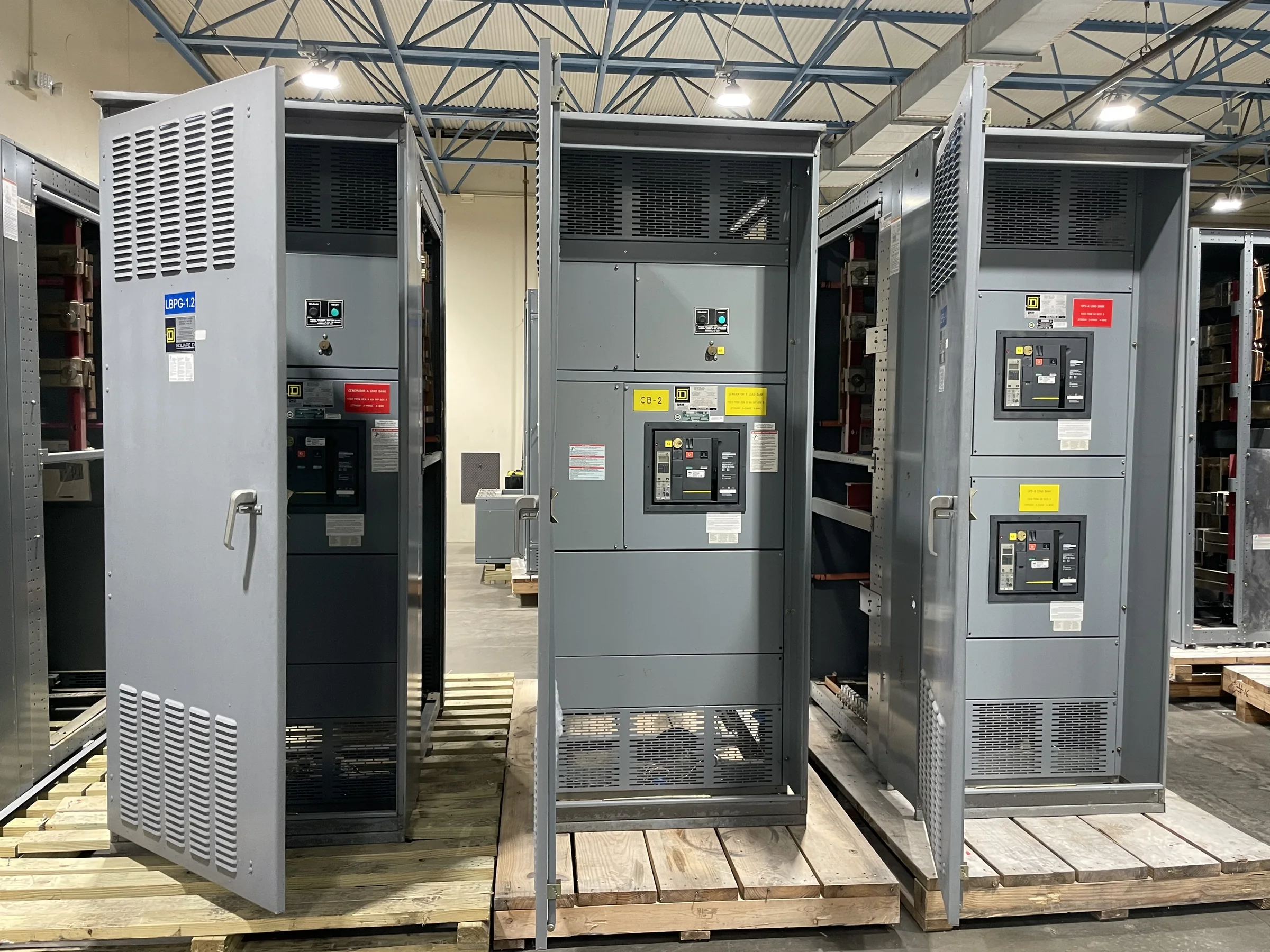
Define the Electrical Scope Around Refinery Loads
Refinery distribution planning starts with the process loads and operating sequences the equipment must serve, not with a generic switchgear lineup. Identify incoming sources, bus arrangements, transformer connections, motor-control interfaces, essential services, and any tie or transfer functions in the project documents. Large motors, variable-frequency drives, and nonlinear loads can affect equipment selection and coordination, so provide load data and operating cases early. Distinguish normal, standby, and emergency loads, and note which process areas must remain available during planned maintenance. These details help the manufacturer develop a proposal that reflects the intended duty and interfaces. Final ratings, protective devices, and configuration depend on the engineered design, applicable codes, and project review; confirm them before release for manufacture.
Account for Hazardous Areas and Refinery Conditions
Refineries can combine corrosive atmospheres, conductive dust, high ambient temperatures, vibration, and hazardous classified locations, but those conditions vary across the site. Tell the equipment manufacturer where the assembly will be installed and provide the environmental and area-classification information established by the project’s qualified engineering team. This matters because enclosure construction, space location, cable entry, ventilation, and equipment interfaces must suit the actual installation; a switchgear room is not automatically equivalent to an outdoor process-area location. Document temperature assumptions, exposure to salt or chemicals, elevation, and any washdown or ingress-protection expectations. Review these requirements alongside the electrical specification rather than relying on a broad description such as “refinery duty.” Site-specific suitability and compliance must be verified for the particular assembly.


Coordinate Protection, Controls, and System Interfaces
Protection settings and control interfaces affect both personnel safety and process continuity. Provide the available fault-current study, grounding approach, utility or generator characteristics, and the project’s coordination requirements so the design team can evaluate the proposed lineup against the system. Identify required metering, relaying, communications, interlocks, remote indications, and connections to plant control systems, including who supplies each component and who verifies signals. A mismatch in control voltage, protocol, terminal arrangement, or trip logic can delay commissioning even when the main bus ratings are appropriate. For refinery projects, clarify the required operating modes and any restrictions on transfer or restart after a disturbance. Final device selection and settings are project-specific and should be reviewed by responsible electrical engineers before equipment release and field energization.
Plan Replacement Work Around Outages and Access
A replacement project may be constrained by a short outage window, an operating plant, and an existing electrical room with little spare space. Before requesting a quote, assemble available one-line diagrams, existing equipment nameplates, room and door dimensions, cable locations, bus connections, and photographs that show access routes. Verify what must remain in service and whether temporary power, phased installation, or tie-in work is part of the project scope; do not assume a new lineup will fit simply because the old one did. The manufacturer can use accurate site information to assess configuration and identify questions before drawings are finalized. The owner’s engineering and safety teams must plan switching, isolation, verification of de-energized conditions, and outage execution. Field dimensions and interface checks remain essential.
Set Submittal, Review, and Procurement Expectations
A useful procurement package makes the technical basis and commercial scope clear enough for an informed comparison. Include the project specification, one-line diagram, load schedule, short-circuit and coordination documents when available, environmental conditions, preferred components, control requirements, and requested submittals. State which items are mandatory and which are acceptable alternatives, and identify required drawing formats, review milestones, inspection expectations, and documentation at shipment. Ask the U.S. manufacturer to clarify exclusions, owner-furnished devices, interfaces, and assumptions in its proposal; unresolved scope can become a costly change after approval. Custom construction and short lead times may be available, but timing depends on the approved design, component availability, review cycles, and project conditions. Confirm current schedule and any applicable evaluation or listing requirements for the specific equipment.
Coordinate Shipment, Receiving, and Installation Readiness
Nationwide shipping does not remove the need to plan the final route into a refinery. Confirm delivery point, receiving hours, carrier access, unloading responsibility, laydown space, storage conditions, and any site security or badging process before scheduling shipment. Large assemblies may need to be divided into shipping sections, so verify section dimensions, weights, lifting provisions, and reassembly responsibilities against the room route and handling equipment. Protect equipment from moisture, contamination, and impact during storage, and follow the manufacturer’s handling and preservation instructions. Before arrival, check that foundations, clearances, cable provisions, grounding points, and installation documents are ready. Coordinate acceptance checks and commissioning responsibilities among the owner, installer, and engineering team; applicable tests, safety procedures, and release to service must follow the project documents and qualified personnel’s direction.