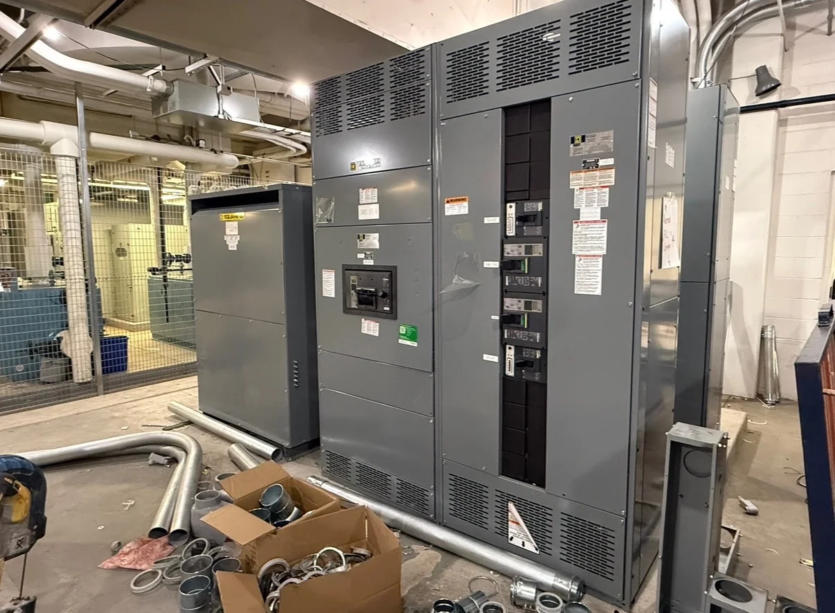
Start with the Utility’s Operating Requirements
A custom utility switchgear package should begin with the electrical duty and operating sequence—not a catalog description. Identify the nominal system voltage, frequency, available fault current, grounding method, continuous load, and the source and load connections the equipment must serve. Then document how the lineup fits the utility’s operating practices: normal and alternate sources, tie operation, isolation points, metering, protection, and any required interlocking. These details influence bus arrangement, protective-device selection, compartment layout, and control wiring. Where the project involves an existing station or distribution system, provide the latest one-line diagram and identify known changes or uncertainties. A clear basis of design helps the manufacturer flag mismatches early; final ratings, configuration, and standards applicability require project-specific engineering review.
Coordinate Protection, Metering, and Controls
Protection and control requirements deserve early coordination because they affect both the switchgear design and the utility’s ability to operate it safely. Specify the intended protective functions, relay or trip-unit interfaces, instrument-transformer requirements, metering points, alarm contacts, communications protocols, and control-power source where these are defined by the project. Confirm which party supplies settings, logic, network equipment, and external cables; an assumption at this boundary can leave commissioning teams with incomplete interfaces. If the utility has standard schematics or approved device preferences, include the current documents in the inquiry rather than relying on model names alone. The final scheme must be checked against system studies and owner standards. Exact device compatibility, functions, and available options depend on the application and approved design.


Resolve Site Conditions Before Layout Approval
The installation environment can determine whether a proposed lineup is practical long before fabrication begins. Provide indoor or outdoor location, ambient temperature range, altitude, moisture or salt exposure, contamination concerns, seismic criteria, and any enclosure or access requirements established for the site. In substations and utility rooms, also verify working clearances, egress, door swing, cable trench or conduit entry, overhead obstructions, and the route from the unloading point to the final pad or floor. A lineup that fits on a one-line drawing may still be impossible to position or connect if these constraints arrive late. Share dimensioned room plans and cable-entry preferences during design review. Environmental provisions, dimensions, and construction details remain subject to project requirements and engineering confirmation.
Set a Realistic Schedule Around Design and Approvals
Schedule planning should account for the decisions and reviews that must precede release to production. A useful request for quotation identifies the required in-service date, bid or approval milestones, drawing-review sequence, site-readiness date, and any outage window that limits installation. Also note whether the project depends on long-lead protective devices, owner-furnished components, utility-standard approvals, or coordination with civil and cable work. The U.S. manufacturer offers custom builds and short lead times, but timing varies with the approved scope, component availability, engineering review, and production conditions; no delivery date should be treated as confirmed until established for the order. Prompt, consolidated comments on submittals reduce avoidable revisions. If the service date is fixed, identify schedule risks early and discuss practical sequencing.
Prepare a Complete RFQ and Review Package
A complete procurement package helps engineers compare proposals on scope rather than on assumptions. Include the one-line diagram, specifications, load and fault data, equipment location, preferred lineup arrangement, cable termination information, protection and metering requirements, and applicable utility or project standards. State what is furnished by others, such as relays, batteries, communications hardware, cables, foundations, or installation labor, so exclusions are visible. Request the proposed equipment description, outline dimensions, connection details, bills of material or device schedules as appropriate, and a list of deviations for review. For low-voltage switchboard assemblies, UL 891 may be relevant when the particular assembly is appropriately evaluated; it does not apply as a blanket certification to medium- or high-voltage equipment. Confirm ratings, standards, labeling, and documentation requirements for the specific project.
Plan Shipping, Receiving, and Commissioning Interfaces
Delivery coordination is part of equipment planning, especially when a utility site has restricted access, limited laydown area, or a narrow outage window. Confirm the receiving location, unloading method, truck and crane access, package dimensions and weights when available, storage conditions, and who will inspect and protect the equipment after arrival. Nationwide shipping is offered, but routing, carrier arrangements, packaging, and delivery timing must be confirmed for the order and destination. Before shipment, align the approved drawings with foundation or housekeeping-pad dimensions, conduit locations, grounding provisions, and cable pull plans. The commissioning plan should identify responsible parties for installation, inspection, testing, relay settings, and energization authorization. All work must follow approved procedures and be performed by qualified personnel with required de-energized conditions and safety controls.