Plan Switchboard Capacity Around Data-Center Loads
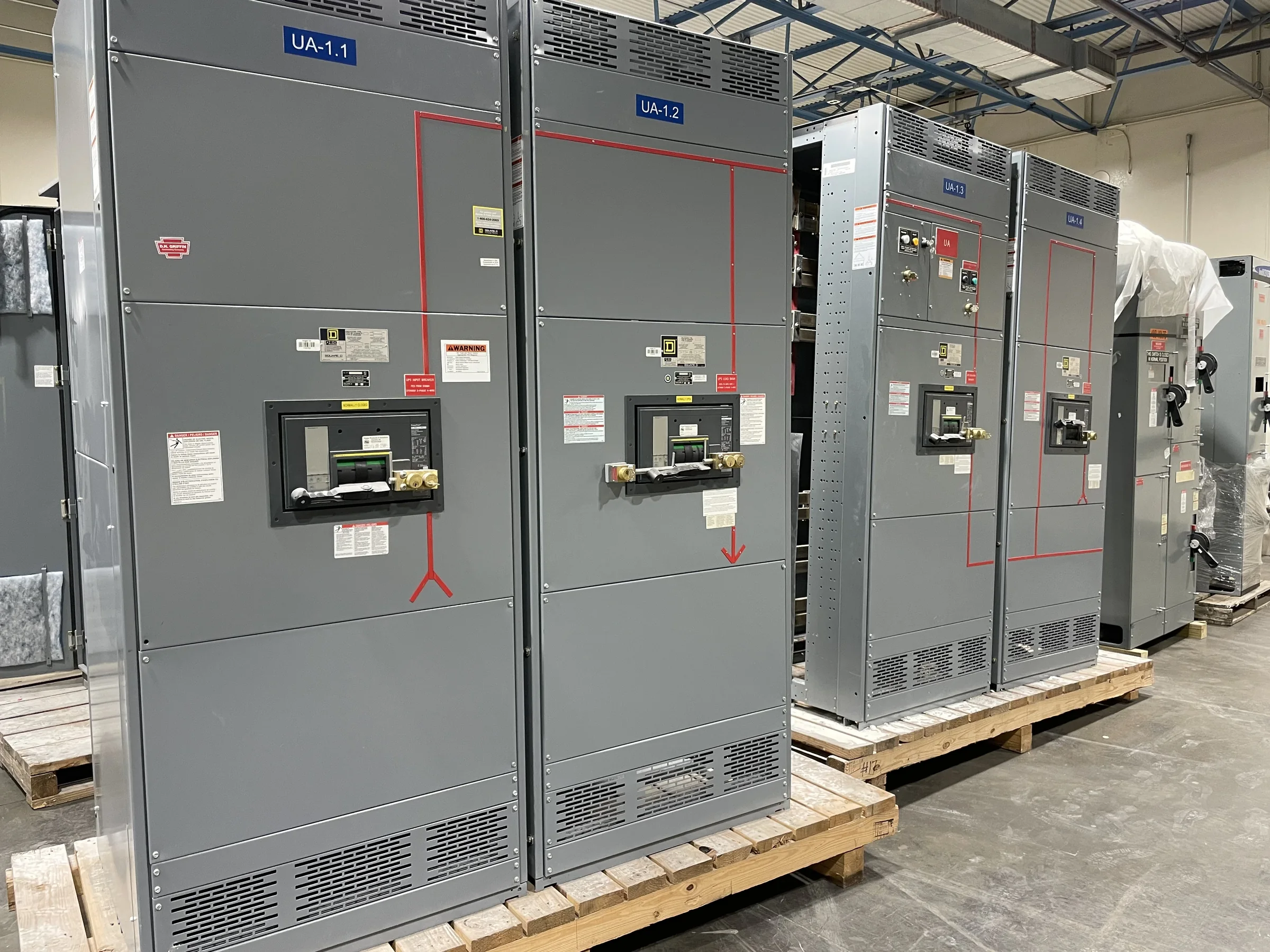
Data-center switchboards must serve a changing mix of loads, not just the initial IT build. Map the intended power path from incoming service through distribution to the equipment served, then identify present demand, planned capacity, redundancy strategy, and expected expansion. Separate critical IT loads from mechanical systems and other facility loads where the project design calls for it; combining unlike loads can obscure operating priorities and complicate coordination. Engineers should also identify how backup sources, transfer equipment, and parallel paths interact with the switchboard. These decisions influence bus arrangement, device selection, physical sections, and provisions for future circuits. Provide the manufacturer with the one-line diagram, load schedule, and operating sequence early so the proposed assembly can be reviewed against the actual design intent.
Coordinate Fault Duty, Protection, and Selectivity
Available fault current and protective-device coordination are central to switchboard selection in a data center. Utility contribution, transformer characteristics, generator behavior, and alternate operating configurations can produce different fault conditions at the equipment. The engineer of record should establish applicable fault-duty and protection requirements for each source and operating mode; the manufacturer can then evaluate the requested assembly and device arrangement against that project information. Selective coordination goals also matter: a fault on one branch should not unnecessarily interrupt upstream distribution serving other critical loads. Do not assume that a device’s frame size, interrupting rating, or trip settings alone establish system coordination. Share current studies, protection criteria, and source details, and resolve exceptions through the project’s engineering review before release for manufacture.


Specify Monitoring, Controls, and Clear Documentation
Monitoring requirements are easier to accommodate when defined before the switchboard layout is finalized. Identify which electrical values, alarms, breaker states, and event information must be available to operators or a building-management system, and specify the intended communications interface where applicable. Confirm who supplies meters, gateways, control power, and field wiring; unclear boundaries can create missed components or late installation changes. The project document package should align the one-line diagram, elementary diagrams, device schedules, bill of materials, and connection details. Review naming conventions and circuit identifiers against the facility’s operating procedures so technicians can trace equipment consistently. Requirements vary by project, so teams should confirm the proposed devices, interfaces, and documentation deliverables during submittal review rather than treating a generic equipment description as sufficient.
Fit the Assembly to the Electrical Room
A switchboard that meets electrical requirements still has to fit the room and support safe service access. Confirm available wall length, working clearances, door swing, access routes, overhead obstructions, floor conditions, and any restrictions on bringing sections through the building. Also consider cable entry direction, conduit or busway interfaces, routing space, and whether the room layout supports the specified lineup arrangement. These constraints affect section placement and installation planning; discovering a doorway or turning-radius problem after shipment can require costly handling changes. Provide dimensioned room plans, entrance details, and interface information during design coordination. The final arrangement, dimensions, and access requirements depend on the selected equipment and applicable project criteria, so verify them against approved drawings before construction and delivery planning proceed.
Coordinate Manufacturing Schedule and Project Changes
Data-center schedules often connect switchboard release to utility coordination, room readiness, commissioning milestones, and downstream equipment installation. Request a project-specific quotation with the required ratings, configuration, documentation, options, and target dates clearly identified. A U.S. manufacturer offering custom builds and short lead times can discuss schedule and scope, but timing depends on the approved design, component availability, review cycles, and order details; confirm commitments for the specific project. Establish submittal and approval responsibilities early, including who resolves comments and controls revisions. Changes to breaker types, metering, interfaces, or physical arrangement after design approval can affect cost and production planning. Maintain a dated revision log and communicate authorized changes through the agreed project process to reduce the chance that construction teams rely on superseded information.
Prepare Delivery, Installation, and Acceptance
Nationwide shipping does not remove the need for a site-specific delivery plan. Confirm receiving hours, unloading equipment, staging capacity, weather exposure, shipment access, and the route from the delivery point to the electrical room. Coordinate shipment sequencing with the approved lineup layout and installation plan, especially when sections must be moved through constrained areas. Before delivery, verify that the site is ready to receive and protect the equipment, and assign responsibility for inspection, storage, and reporting any shipping damage. Acceptance planning should identify the documents, inspections, and checks required by the project team before energization; installation and testing must follow approved procedures and be performed by qualified personnel, with equipment de-energized for work. Confirm final requirements, compatibility, and shipping arrangements with the project team and manufacturer.