Map Essential Loads Before Selecting the Switchboard
Hospital distribution begins with how loads are classified and served, not with a catalog frame size. The design team should identify normal, legally required standby, and other essential loads according to the project’s adopted codes and the facility’s electrical design criteria. Patient-care areas, life-safety systems, clinical support spaces, imaging, laboratories, and building services can have different continuity requirements; do not assume they belong on one bus or transfer arrangement. Confirm which loads are served by generators, UPS systems, or other sources, and where transfer equipment sits relative to the switchboard. These decisions affect sections, bus arrangements, feeder provisions, and coordination studies. Early agreement among the electrical engineer, hospital facilities staff, and procurement team reduces late redesign and helps ensure the equipment matches the approved one-line diagram.
Coordinate Capacity, Fault Duty, and Protective Devices
A switchboard must fit the system’s calculated demand and withstand the available fault current at its point of installation. Ask the engineer to provide the latest load schedule, transformer data, utility or generator source information, and short-circuit and coordination study requirements before requesting a firm equipment configuration. Future expansion may call for spare spaces or planned feeder provisions, but simply adding unused capacity does not establish that the assembly or protective devices are suitable for a later load. Breaker types, ratings, trip functions, and selective-coordination objectives need to align with the engineered study and applicable project requirements. Because hospital systems can include multiple sources and ties, confirm the intended operating modes and interlocking approach. Final ratings and device selections remain project-specific and require engineering review.


Resolve Space, Access, and Service Constraints
In an occupied hospital or a tight new-build electrical room, the switchboard’s footprint is only one part of fit. Confirm room dimensions, working clearances, door swings, equipment elevations, cable entry and bending space, conduit locations, and the path from receiving area to final position. Structural loading, floor openings, seismic requirements, environmental conditions, and access for future maintenance may also affect the layout. A lineup that fits on a plan can still be impossible to move through a corridor, turn through a doorway, or position without disrupting adjacent services. Share architectural and electrical-room drawings early, and flag elevators, loading docks, restricted routes, and infection-control boundaries. The manufacturer can develop equipment around stated project constraints, while the design team verifies code clearances and site readiness.
Plan Replacement Work Around Continuity of Care
Replacing an existing switchboard in an operating hospital requires a carefully engineered transition plan because connected loads may support patient care and critical building functions. Establish which existing feeders and sources must remain available, what temporary distribution or outage windows the project allows, and who authorizes switching and shutdowns. Field-verified dimensions, cable terminations, bus connections, grounding, and protective-device interfaces are essential; legacy drawings may not reflect conditions behind the equipment. A replacement or retrofit scope should distinguish new assembly work from site demolition, temporary power, testing, and final reconnection responsibilities. All work must follow approved safety procedures, with equipment de-energized before work where required and no assumption that energized work is acceptable. Early coordination with facilities, infection prevention, clinical leadership, and the electrical contractor helps limit operational surprises.
Prepare a Complete Submittal and Procurement Package
A useful request for quotation gives the manufacturer enough information to identify the intended assembly without treating an incomplete design as a final specification. Include the one-line diagram, panel and feeder schedules, system voltage and frequency, source and tie arrangement, available fault-current data, protective-device requirements, room and access drawings, and applicable project specifications. Identify required drawings, shop-drawing review stages, wiring diagrams, nameplates, testing documentation, and operation and maintenance materials. If a low-voltage switchboard assembly must be evaluated to UL 891, state that requirement clearly and confirm the exact assembly scope and labeling expectations; it does not apply as a blanket certification to medium- or high-voltage equipment. Resolve exceptions in writing before release. A coordinated package helps engineers review details and gives procurement a sound basis for comparing proposals.
Align Build Timing, Delivery, and Site Readiness
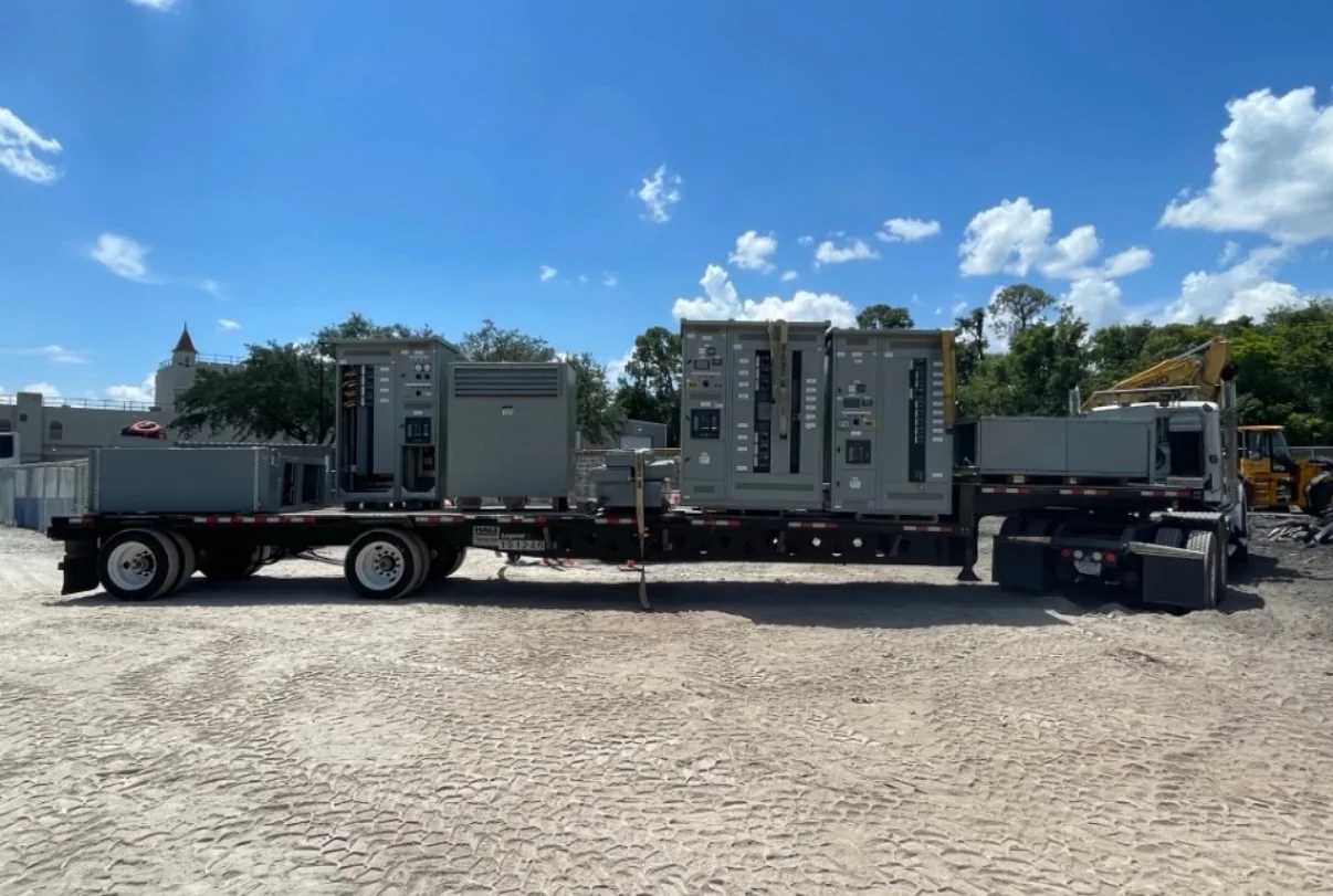
Hospital projects often depend on sequenced construction, limited receiving space, and tight installation windows, so discuss schedule assumptions before equipment release. Provide the required on-site date, drawing approval milestones, site access rules, receiving hours, unloading capability, storage conditions, and whether deliveries must be phased. U.S. manufacturing, American components, custom builds, short lead times, and nationwide shipping may be available offerings, but actual configuration, component availability, approvals, and freight planning affect each project schedule. Confirm current timing with the manufacturer rather than relying on a general estimate, and do not schedule shutdowns around an unconfirmed delivery date. Before shipment, verify that the electrical room is complete, the route is clear, and the contractor is ready to receive and install the lineup. Clear ownership of these checks reduces avoidable storage, handling, and commissioning delays.