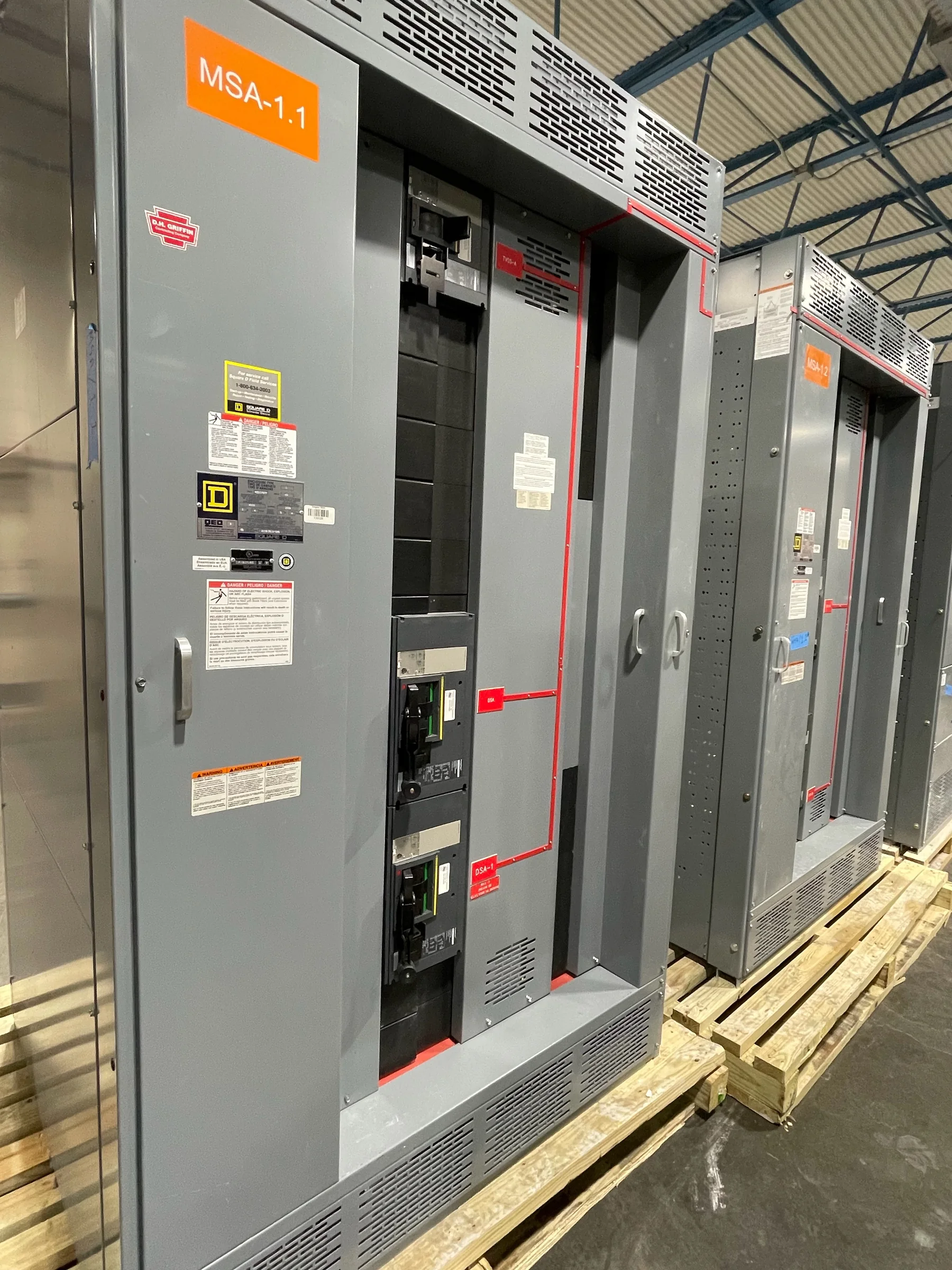
Start With the Facility’s Load and Operating Plan
An industrial switchboard must fit the electrical system it serves and the way the facility operates, not just the available wall space. Gather the service voltage, phase, frequency, source configuration, available fault-current information, and expected load before settling on an arrangement. Identify major loads such as motors, process lines, HVAC, lighting, and standby or alternate sources, and note which operations cannot tolerate an interruption. This information helps engineers assess bus and protective-device requirements, feeder count, and whether future circuits need to be accommodated. Load growth should be based on a credible expansion plan rather than an arbitrary spare-capacity assumption. Confirming these inputs early matters because late changes can affect layout, component selection, coordination, and the scope of replacement or retrofit work.
Coordinate Protection, Interrupting Capacity, and System Studies
The switchboard’s protective devices must be considered in the context of the complete distribution system. Provide current short-circuit and coordination studies when available, along with the upstream protective-device data and details for downstream equipment. The available fault current at the installation point affects the interrupting and withstand requirements; a rating cannot be selected responsibly from load alone. Coordination goals also depend on the consequences of an outage: a process facility may want a fault on one feeder to affect as little equipment as practicable, while still meeting applicable safety and engineering requirements. Ask the project engineer to identify the governing codes, standards, and study assumptions. This review matters because an apparently suitable lineup can be incompatible with the system or require changes elsewhere in the distribution chain.


Resolve Layout, Access, and Environmental Conditions
A workable electrical design has to fit the room and remain accessible for installation, operation, inspection, and maintenance. Share dimensioned room drawings, equipment elevations, door and aisle locations, cable-tray routes, conduit entry areas, floor conditions, and the planned path from the receiving area to the final location. Check clearances against the applicable code and the equipment’s installation instructions rather than relying on a rough footprint. Industrial environments add practical concerns: dust, moisture, corrosive substances, vibration, heat, and washdown exposure can affect enclosure and installation choices. Identify those conditions during specification, including any need to separate equipment from process hazards. Resolving these constraints before fabrication helps prevent delivery-day obstructions, unplanned field modifications, and equipment that cannot be safely serviced.
Specify the Right Assembly and Document Its Interfaces
A complete procurement package should describe the required distribution function as well as the physical assembly. List incoming and outgoing connections, feeder quantities, metering needs, control or communications interfaces, neutral and grounding arrangements, and any source-transfer or tie functions relevant to the project. Clearly distinguish required features from preferences, and identify equipment that must interface with existing transformers, generators, protective relays, or downstream panels. For low-voltage switchboard assemblies, UL 891 may be relevant when the assembly is appropriately evaluated for that standard; it is not a blanket certification for medium- or high-voltage equipment. Request submittal drawings and component information for engineering review, with revision control and approval responsibilities defined. Clear documentation matters because mismatched interfaces or assumptions can delay approval and complicate commissioning.
Plan Schedule Around Approvals, Components, and Shutdowns
A short stated lead time is not a substitute for a project-specific schedule. Before placing an order, discuss drawing review, approval cycles, design changes, component availability, fabrication sequence, inspection requirements, and the requested ship date with the manufacturer. Identify milestones that depend on other parties, such as approved one-lines, final room dimensions, utility information, or completed site work. For a replacement project, coordinate the equipment schedule with the facility’s outage window and temporary operating plan; the new board’s arrival does not by itself make a shutdown safe or the installation ready. De-energized work and the site’s approved safety procedures must be planned by qualified personnel. Early schedule alignment matters because unresolved engineering inputs or late approvals can affect both production planning and the facility’s ability to switch over.
Coordinate Freight, Receiving, and Final Turnover
Nationwide shipping does not remove the need to plan how a large assembly will reach its installation point. Confirm the delivery address and site contact, receiving hours, unloading equipment, dock or curb access, route restrictions, indoor staging area, and any limits on truck size or delivery timing. Compare the shipping configuration with door widths, turning space, elevators, floor loading, and the intended movement path; a lineup that reaches the property may still be unable to enter the electrical room. Agree on what documentation is needed at delivery and for turnover, such as final drawings, equipment identification, and available operation or maintenance information. Inspect the shipment on receipt and document any visible damage before moving it. These details matter because unclear receiving responsibilities can create avoidable handling risks, storage problems, or installation delays.