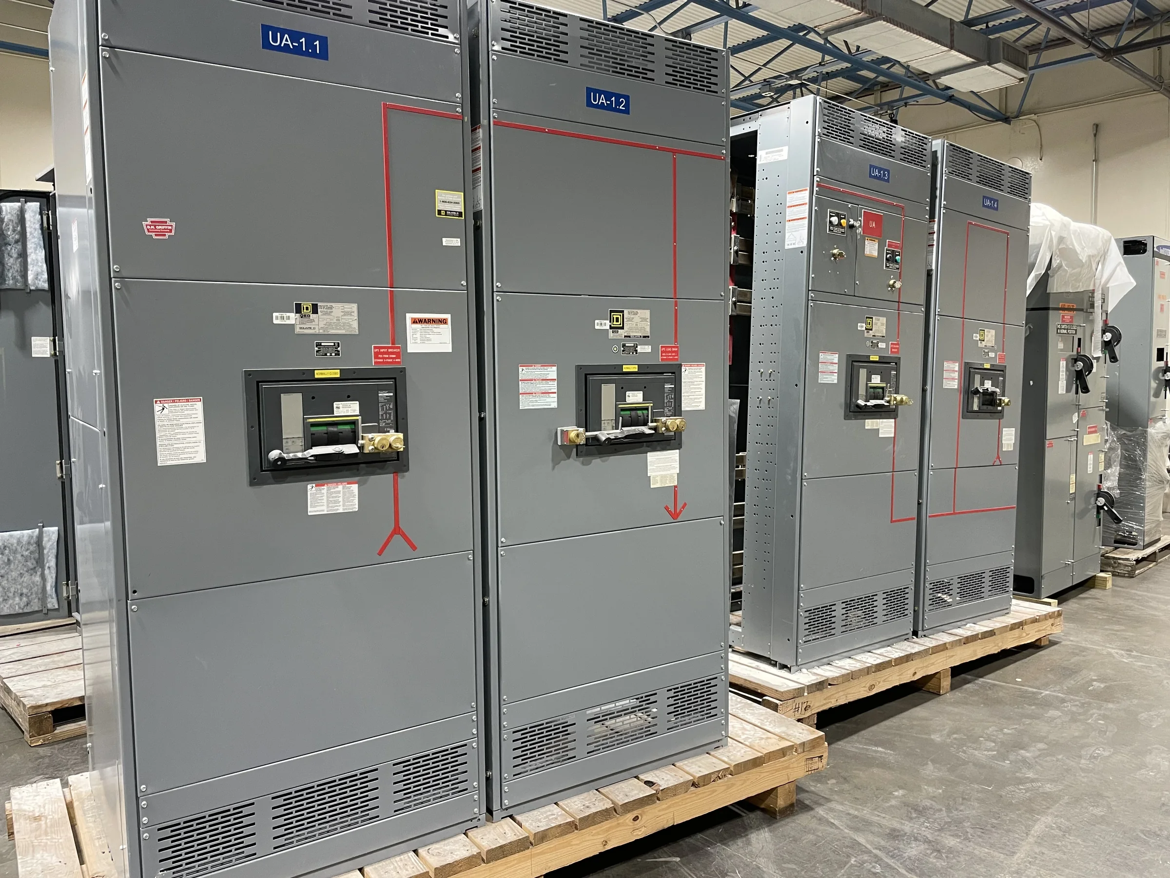
Distribution Planning for Port Operations
A port switchboard must serve more than a collection of loads: it supports cargo handling, terminal buildings, maintenance areas, lighting, and other services whose operating schedules may differ. Start by mapping existing and planned loads, identifying which equipment must remain available during maintenance, and clarifying where shore power or other specialized systems connect to the distribution network. These decisions shape the bus arrangement, feeder count, protective-device coordination, and space reserved for future circuits. For terminals expanding in phases, document which loads belong to each phase and whether temporary operating arrangements are expected. A manufacturer can use that information to develop a new assembly around the project requirements, while final ratings, configuration, and compatibility remain subject to engineering review.
Marine Exposure and Equipment Placement
Salt-laden air, moisture, wind-driven rain, dust, and temperature variation can affect equipment selection and enclosure planning at waterfront sites. The actual exposure depends on whether the switchboard is inside a conditioned electrical room, in a ventilated terminal building, or in a location subject to direct weather and corrosive contaminants. Provide the intended installation environment, enclosure location, access conditions, and any project-defined environmental requirements when requesting a quote. These details matter because an enclosure or component choice suitable for a protected room may not suit a harsher setting. Consider drainage, ventilation, corrosion-control requirements, and room clearances as part of the design coordination. Confirm environmental suitability and any required evaluations for the specific assembly rather than assuming one construction fits every marine terminal.


Service Continuity, Protection, and Expansion
Unplanned outages can interrupt vessel support, cargo movement, security systems, and terminal operations, so protection and maintenance needs should be considered alongside initial capacity. Share the available system information, including source characteristics, fault-current data when established, existing protective-device details, and the intended load connections. Engineers can then review coordination objectives and identify information still needed before selecting an arrangement. Where operations require planned maintenance or staged upgrades, clarify whether alternate sources, tie sections, or future feeder positions are part of the project scope; do not assume these features are included by default. A clearly documented expansion plan can help avoid a crowded lineup or disruptive later modifications. Final protection settings, ratings, and interfaces require project-specific engineering and verification.
Drawings and Information for a Clear Quote
A useful quotation starts with a defined technical package, not just a requested amperage or a reference to existing gear. Include one-line diagrams, load schedules, system voltage and frequency, available fault-current information, required feeder quantities, cable-entry preferences, and any owner or engineer specifications available. Identify the installation location, room dimensions, access route, and connection constraints as well. If replacing existing equipment, provide nameplate details and interface drawings where available, while treating compatibility as something to verify rather than presume. Flag required inspections, documentation, testing, or submittal milestones in the procurement schedule. This information helps the manufacturer identify open engineering questions early, compare proposed scope with the project documents, and prepare a quote that is less likely to omit a critical connection or site requirement.
Schedule and Delivery Coordination at the Waterfront
Port projects often share constrained access roads, security-controlled gates, active yards, and limited staging space. Those conditions can affect how a new switchboard is packaged, transported, received, and moved to its final room, even when the electrical design is settled. Discuss the delivery destination, unloading responsibility, access windows, site contact process, and any carrier or terminal restrictions before placing an order. Confirm the assembly’s shipping dimensions and handling requirements against doors, corridors, lifting provisions, and route turns; a lineup that fits the room may still be difficult to bring inside. A U.S. manufacturer can discuss project timing and nationwide delivery coordination, but availability and schedule depend on the final scope and current project conditions. Build realistic review, approval, and site-readiness steps into procurement planning.
Submittals, Installation, and Project Closeout
Before release for manufacture, compare approved submittals with the one-line diagram, equipment schedule, room layout, and specified interfaces. Resolve discrepancies in feeder destinations, metering, control wiring, cable access, and future provisions before they reach the installation stage. For a low-voltage switchboard project, UL 891 may be relevant when the assembly is appropriately evaluated to that standard; it should not be treated as a blanket certification for all equipment or voltage classes. State the project’s required standards and evaluation expectations in the specification, then confirm their applicability to the proposed assembly. Plan installation, inspection, testing, and energization with qualified personnel under applicable site procedures. Closeout documents should reflect the delivered configuration and agreed scope, giving facility teams a dependable reference for maintenance and future changes.