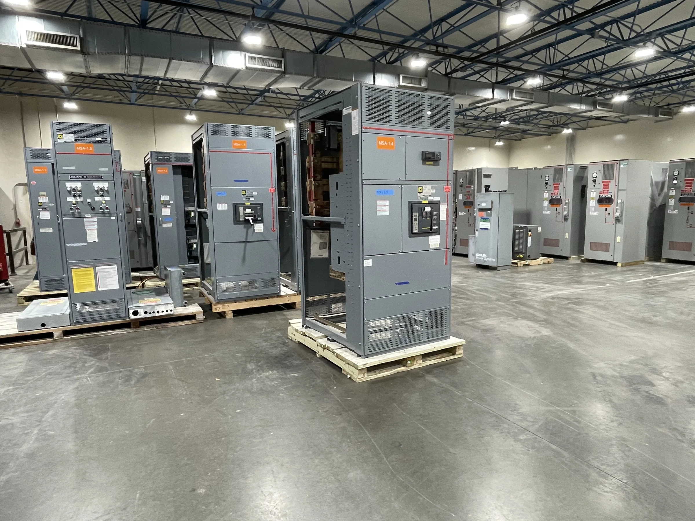
Plan Distribution Around Plant Loads and Operating Modes
Power plants depend on electrical distribution for both generation-related auxiliaries and the facilities that keep the site operating. Start switchboard planning with an up-to-date load list that distinguishes normal, standby, essential, and future loads, then identify how those loads change during startup, shutdown, maintenance, and abnormal conditions. This operating picture helps the project team evaluate bus arrangements, source connections, transfer requirements, and the consequences of taking a section out of service. It also prevents a common procurement problem: selecting an assembly from a single peak-load figure without accounting for operating sequences or planned expansion. Coordinate the preliminary one-line diagram with the plant’s electrical engineer and protection team. Final ratings and configuration depend on the system study, applicable codes, and project requirements.
Define the Electrical and Environmental Requirements
A switchboard installed in a power plant must suit its actual electrical system and location, not just its nominal voltage. The specification should identify system voltage, frequency, available fault current, grounding method, incoming sources, feeder quantities, and required protective-device functions. Site conditions matter too: indoor or outdoor placement, ambient temperature, altitude, dust, moisture, corrosive agents, vibration, and available ventilation can affect equipment selection and enclosure details. These factors should be documented early, because omissions can trigger redesign or complicate review of the proposed equipment. Where a project requires a low-voltage switchboard evaluated to UL 891, state that requirement for the applicable assembly; it does not establish a blanket listing for medium- or high-voltage gear. Confirm standards and acceptance criteria for each scope.


Coordinate Protection, Controls, and Interfaces
Plant distribution equipment rarely stands alone. Protection settings and device choices must coordinate with upstream sources, downstream loads, generator controls, transfer schemes, and any plant monitoring or supervisory systems included in the project. Provide the manufacturer with approved one-line diagrams, device schedules, control narratives, interconnection details, and relevant study results when available. Clear interface documents reduce the risk of mismatched trip functions, unavailable status points, or control wiring that conflicts with the plant’s operating philosophy. They also give reviewers a practical basis for checking how a proposed lineup fits the broader electrical design. Identify which party supplies relays, meters, communications hardware, and external wiring; responsibilities vary by project. Final coordination, protection settings, and integration should be verified by qualified project personnel before installation and commissioning.
Resolve Layout, Access, and Replacement Constraints
In an operating plant, the equipment footprint is only one part of the installation question. Check room dimensions, ceiling height, door and corridor clearances, floor loading, cable entry and bending space, ventilation, working clearances, and the route from the unloading point to the final location. Existing facilities may have limited access or legacy conduits that constrain lineup orientation and section arrangement. For replacement work, accurate field dimensions, photographs, cable information, and existing drawings help the engineering team assess what can be reused and what must change. A mismatch discovered after shipment can affect rigging plans, outage work, and construction sequencing. Confirm the site’s lifting and handling arrangements, foundations, anchorage, and installation responsibilities with the project team; these details are site-specific and should not be assumed.
Build Procurement Around Complete Project Information
A useful request for quotation gives suppliers enough detail to identify the intended scope without treating preliminary data as final. Include the project schedule, one-line diagram, load and feeder schedules, required devices and accessories, enclosure conditions, preferred component requirements, applicable standards, drawing submittal expectations, and any known interface boundaries. Mark unresolved values and identify who will approve them. This makes technical exceptions and assumptions easier to compare across proposals, while reducing the chance that a low initial price excludes a needed feature. A U.S. manufacturer can discuss custom builds and American components for the project, but exact component selection, compatibility, ratings, and availability must be confirmed against the specification. Request a clear list of deviations and required customer information before advancing the design.
Align Manufacturing, Submittals, and Delivery With the Site
Power-plant schedules often connect equipment delivery to outage windows, construction milestones, and commissioning plans. Share required dates and the consequences of a missed handoff during quotation, then confirm the schedule against the approved design, component availability, review cycles, and manufacturing scope. Short lead times may be available, but timing is project-specific rather than a guarantee. Agree on drawing-submittal milestones, review responsibilities, approved-for-construction status, shipping terms, packaging expectations, and delivery access before release. Nationwide shipping can support projects across the United States, yet receiving arrangements still depend on the site: check truck access, unloading capacity, storage conditions, weather exposure, and whether shipments must be sequenced by lineup or installation phase. A coordinated plan gives procurement, engineering, and the facility team a clearer basis for managing schedule risk.