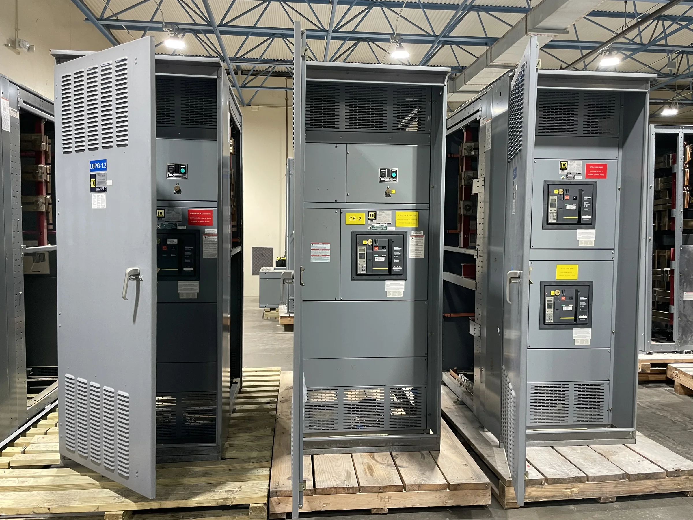
Define the Utility Service and Distribution Boundary
Start with the one-line diagram and identify exactly where the switchboard sits in the utility’s distribution scheme. Record the incoming source, normal and alternate feeds, downstream circuits, metering points, and any connection to customer-owned equipment. This boundary affects equipment arrangement, ownership, operating responsibility, and the information required from the serving utility. Confirm whether the project is for a substation auxiliary system, operations facility, water or wastewater site, communications building, or another load; these applications do not impose identical requirements. Request utility service data and applicable interconnection criteria early, including available fault-current information where it can be provided. If source characteristics or ownership demarcation remain unclear, flag them as open engineering items rather than assuming a standard arrangement.
Coordinate Ratings, Protection, and System Studies
Switchboard ratings must be selected against the actual system and the project’s governing criteria, not inferred from a facility’s size. The engineer should coordinate voltage, continuous current, short-circuit withstand or interrupting requirements, protective-device functions, and the intended operating configuration with the available study data. Utility sources can change as feeders, transformers, or tie arrangements change, so confirm which fault-current assumptions apply to the equipment location and whether planned system changes must be considered. The protection scheme also needs to coordinate with upstream utility devices and downstream loads; an incompatible trip strategy can compromise selectivity or service continuity. Provide the manufacturer with approved drawings and study assumptions, and identify unresolved values. Final ratings, device selection, and applicable standards require project-specific review.


Specify Metering, Controls, and Operational Access
Utility facilities may need more than power distribution: metering, status indication, alarms, control interfaces, and provisions for future circuits can influence the lineup and internal layout. Define which signals are required, where they terminate, who supplies associated relays or communications equipment, and what interface information must be exchanged with the utility or site controls team. Also describe how operators will read meters, inspect devices, and perform approved maintenance under the facility’s safety procedures. Door swing, working space, cable access, and nearby walls or piping can make a nominally suitable lineup difficult to operate. Show those constraints on the room plan rather than leaving them to installation. Confirm whether spare capacity means physical spaces, installed devices, or only electrical capacity; the distinction affects cost and planning.
Match the Assembly to the Site Environment
The installation environment should shape enclosure, materials, cable-entry, and access decisions. Utility equipment may be located in conditioned control buildings, pump stations, outdoor enclosures, or spaces exposed to moisture, dust, temperature variation, vibration, or corrosive agents. Describe actual conditions and expected operating ranges instead of relying on a broad label such as “industrial.” Review elevation, ventilation, drainage, housekeeping, and the chance of water intrusion; these factors can affect equipment suitability and long-term maintainability. Confirm whether conductors enter from above or below and whether the planned route leaves room for bending, pulling, and termination. A switchboard designed around an assumed room or environment may require costly site changes. Final construction details and ratings depend on documented conditions and engineering review.
Prepare a Complete Submittal and Review Package
A useful purchase package helps engineering, operations, and procurement evaluate the same scope. Include the one-line diagram, load and circuit schedules, site layout, service information, control and metering requirements, applicable project specifications, and any approved study results. Identify the required document list and review milestones, such as outline drawings, connection details, bills of material, and operation or maintenance information, while confirming what the manufacturer can provide for the particular build. Mark deviations and unresolved questions clearly; buried assumptions can lead to redesign or delayed approval. Review physical dimensions and termination locations against the room and cable plan before release for manufacture. If equipment must interface with existing gear, supply verified nameplate and connection data rather than relying on model names alone.
Plan Build Timing, Delivery, and Installation Readiness
Discuss schedule and delivery requirements with the manufacturer when the specification is being developed, not after drawings are complete. Custom configurations, component selections, review cycles, and changes in scope can affect the production sequence; timing and availability must be confirmed for the specific project rather than treated as guaranteed. Provide the required on-site date, receiving hours, unloading method, access restrictions, and whether the route includes narrow doors, ramps, elevators, or overhead obstructions. Confirm shipment dimensions and handling arrangements against the site plan, and coordinate storage conditions if the installation area is not ready. Before equipment arrives, align the approved drawings, foundation or housekeeping-pad details, conduit locations, and installation responsibilities. Nationwide shipping can support projects across the United States, but delivery coordination remains site-specific.