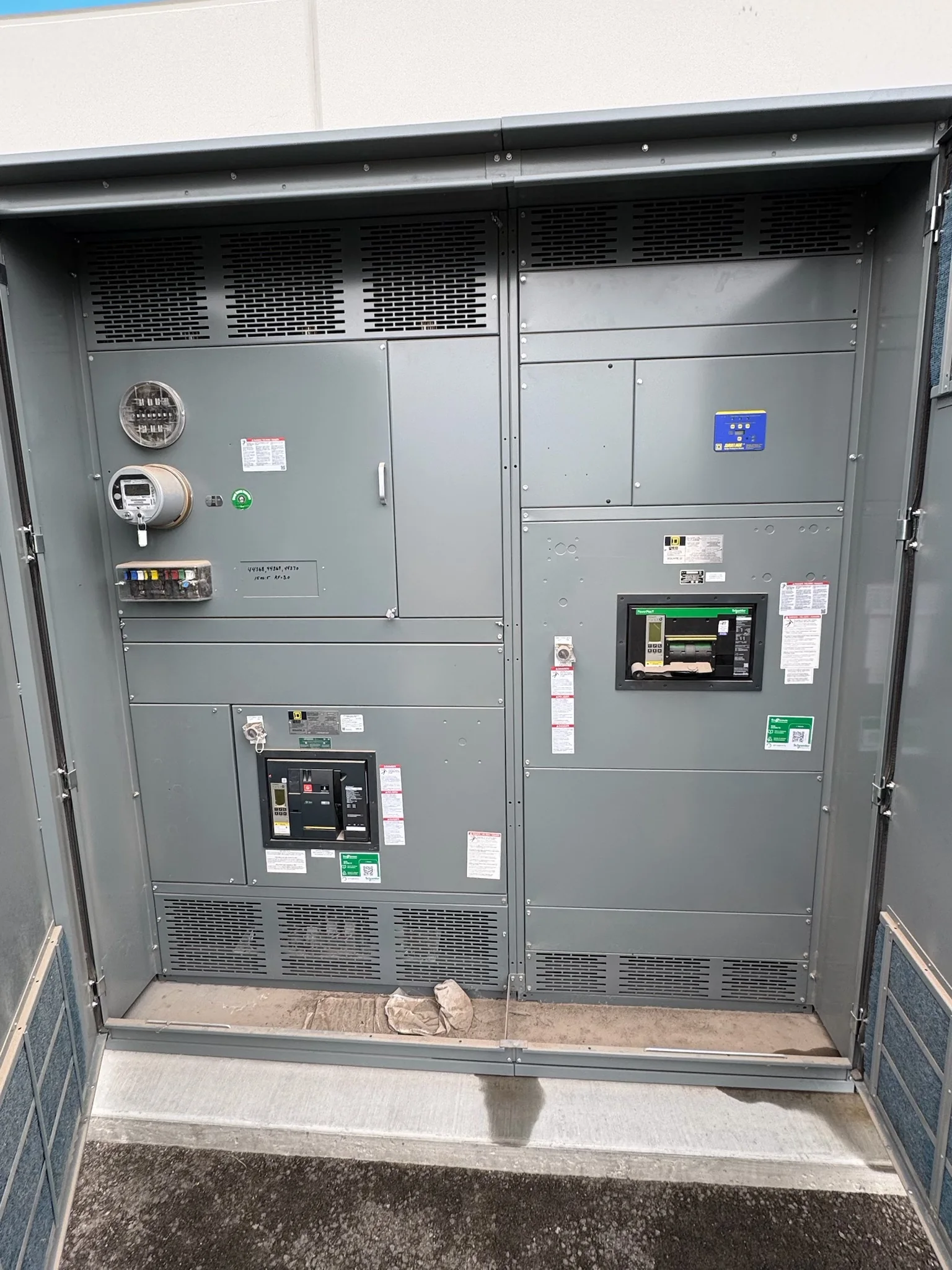
Coordinate Distribution with the Treatment Process
Wastewater facilities depend on electrical distribution for processes that may operate continuously, cycle with flow, or respond to changing tank levels. A switchboard project should begin with the process loads it will serve: pumps, blowers, screens, mixers, chemical-feed equipment, and supporting systems. Confirm which loads are essential, how they start, and whether operation depends on a particular sequence or control interface. These details influence feeder arrangements, protective-device coordination, available space, and how operators isolate equipment for maintenance. Procurement teams can help prevent scope gaps by sharing process and electrical one-line diagrams, load schedules, motor information, and control-system requirements early. Final ratings, configurations, and compatibility depend on project conditions and engineering review; they should not be inferred from a general application description.
Account for Moisture, Corrosion, and the Installation Area
A switchboard’s surroundings can be as important as its connected loads. Wastewater buildings may expose electrical equipment to humid air, condensation, washdown, corrosive gases, or airborne contaminants, while an outdoor installation faces weather and temperature conditions. The project team should identify the actual location, enclosure environment, ventilation, access, and any separation from process areas before equipment is specified. This matters because an unsuitable installation environment can shorten service life or complicate safe inspection and maintenance. Provide available room layouts, equipment elevations, environmental requirements, and details of nearby piping or drains so the proposed assembly can be evaluated for the intended space. Enclosure construction and environmental suitability are project-specific; confirm requirements with the responsible engineer rather than assuming a standard configuration will fit every wastewater site.


Define Capacity, Protection, and Operating Continuity
Pump stations and treatment plants may have uneven demand, frequent motor starts, or equipment that must remain available while another unit is serviced. Those operating realities make the load list and system study essential inputs, not paperwork to complete after ordering. Identify present loads, planned additions, utility or generator sources, and the operating scenarios the distribution equipment must support. Engineers use these inputs to establish ratings and evaluate protective-device coordination, fault-current withstand, and integration with upstream and downstream equipment. Where continuity is important, clarify the facility’s transfer, redundancy, and maintenance approach; a switchboard alone does not determine the complete system’s reliability. Avoid selecting ratings by matching an existing nameplate without checking the current electrical conditions, applicable requirements, and proposed changes. Final design decisions require project-specific engineering.
Make Replacement and Retrofit Scope Verifiable
Replacing an existing assembly in an operating facility can involve constraints beyond matching its nominal voltage or footprint. The incoming equipment must be checked against available fault current, bus and feeder arrangements, protective-device functions, cable entry, grounding, control connections, and the physical route into the electrical room. Existing drawings may not reflect later field changes, so confirm critical dimensions and connections through qualified site review. Document what remains, what will be removed, and which interfaces are included in the replacement scope; unclear boundaries can create costly work during an outage. Plan de-energized work, lockout/tagout, access restrictions, and any required temporary operating measures with the facility’s authorized personnel. Compatibility and retrofit feasibility cannot be guaranteed from photographs or legacy labels alone; verified site information and engineering review are necessary.
Prepare a Complete Specification and Submittal Package
A useful request for quotation gives the manufacturer enough information to identify the intended assembly and flag unresolved questions. Include the one-line diagram, load schedule, system voltage and grounding information, available fault-current data, enclosure location, dimensional limits, cable-entry preferences, and specified standards or project requirements. Add control schematics, communications needs, and device preferences when they affect the equipment scope. For low-voltage switchboard assemblies, UL 891 may be applicable when the assembly is appropriately evaluated; it does not establish blanket coverage for medium- or high-voltage equipment. During submittal review, compare drawings and component schedules against the approved design, site clearances, and coordination study. Clear document responsibilities and timely review matter because late revisions can affect fabrication planning, interfaces, and the project schedule.
Plan Production, Shipment, and Site Readiness Together
Discuss schedule and delivery requirements with the manufacturer when the project scope is being defined, not only after drawings are approved. Custom configurations, component selections, design review, and approval cycles all affect the path from specification to shipment; timing and availability must be confirmed for the individual project. For wastewater sites, delivery planning should also account for restricted truck access, security check-in, unloading equipment, indoor staging, door and corridor dimensions, and the route to the electrical room. Share the receiving location’s constraints and requested delivery window so logistics can be coordinated against site readiness. Before shipment, confirm that foundations or housekeeping pads, cable pathways, clearances, and receiving personnel are prepared. Nationwide shipping and short lead times are offered, but neither establishes a guaranteed delivery date; obtain project-specific confirmation.