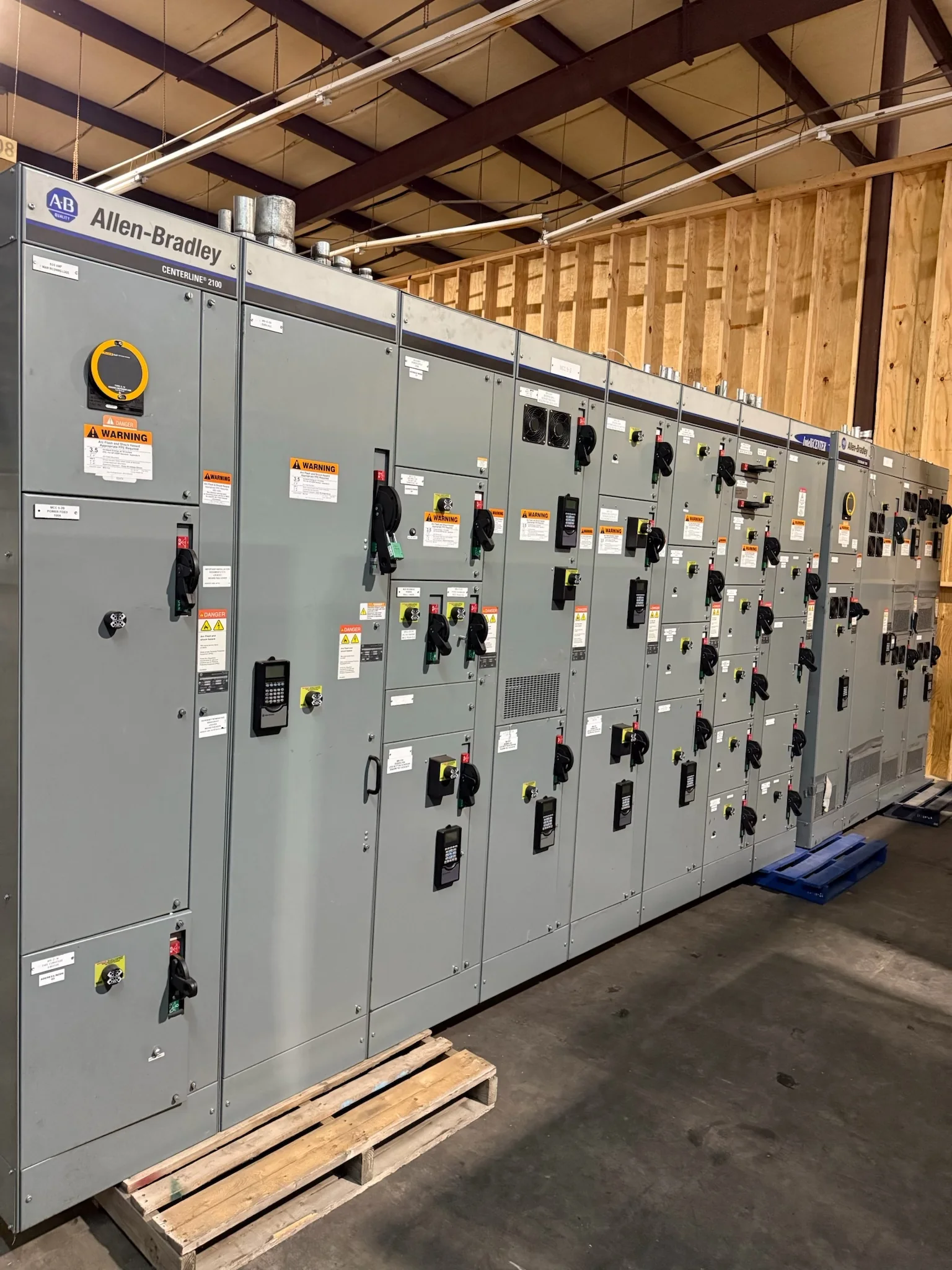
Define the Switchboard Around the Load
For a Humble facility, start switchboard planning with the loads it must serve—not with a catalog label or an assumed standard lineup. Collect the one-line diagram, connected and calculated demand, source information, voltage, phase, frequency, and required feeder count. Note which loads are motors, electronic equipment, HVAC, process machinery, or life-safety systems; their operating and starting characteristics affect distribution choices and coordination. Identify any planned additions, because spare spaces, future capacity, and physical room for expansion are different requirements. The manufacturer can use this information to develop a project-specific proposal, but final ratings and configuration depend on engineering review and the applicable installation conditions. Clear inputs help prevent late redesign, mismatched protective devices, or an assembly that cannot serve the intended loads.
Confirm Fault Duty and Protection Requirements
Available fault current at the proposed switchboard location is a critical design input. Ask the electrical engineer or serving utility for the applicable source data, and provide the expected transformer information, conductor details, and grounding arrangement where available. The selected assembly and protective devices must be suitable for the system conditions and coordinated with upstream and downstream equipment; interrupting ratings, withstand ratings, and selective coordination are not interchangeable terms. If an existing board is being replaced, do not assume its nameplate values remain appropriate after a utility, transformer, or feeder change. Share current studies, protective-device schedules, and project criteria during quoting. The specific rating, device combination, and compliance path require project review, so an early check is more useful than trying to resolve fault-duty questions after fabrication.


Fit the Assembly to the Electrical Room
Room dimensions and service access can constrain a switchboard even when its electrical requirements are settled. Measure the available wall length, ceiling height, door openings, turning paths, floor conditions, and the space needed to position and secure the equipment. Confirm working space and access requirements with the project’s qualified electrical professionals and applicable codes; do not treat the equipment footprint as the full room-clearance requirement. Review cable entry direction, conduit locations, bend space, and whether conductors approach from above or below. In existing Humble-area buildings, additions may have to share a crowded electrical room with piping, HVAC, or other services. A dimensioned plan and site photographs help identify conflicts early, while final fit and installation details remain subject to field verification and approved drawings.
Account for Humidity, Heat, and the Installation Environment
The installation environment affects enclosure selection, equipment arrangement, and long-term maintenance. For a Humble project, tell the design team whether the switchboard will be indoors, outdoors, in a conditioned room, or in a space exposed to moisture, dust, corrosive agents, or temperature extremes. Gulf Coast humidity and seasonal heat make ventilation, condensation risk, and room conditions practical questions, not assumptions to leave until commissioning. Provide available environmental criteria and describe nearby processes that could introduce washdown, chemical exposure, or airborne contaminants. Enclosure type and any environmental provisions must match the actual location and project requirements; no single option is appropriate for every site. The facility team should also consider whether equipment access and maintenance can be maintained without disrupting adjacent operations.
Review Drawings, Submittals, and Scope Before Release
A useful submittal package lets the engineer, contractor, and owner confirm what is being supplied before the build is released. Compare the proposed one-line diagram, arrangement drawings, dimensions, bus and feeder details, device schedule, and connection points against the project documents. Identify who provides breakers, metering, control wiring, upstream protection, and field connections; unclear boundaries can create change orders or installation gaps. Record any deviations and resolve them through the project’s review process rather than relying on verbal assumptions. If a low-voltage switchboard assembly is being specified to UL 891, confirm the requirement and its applicability for that exact assembly. UL 891 is not a blanket certification for all switchgear or medium- and high-voltage equipment. Approved drawings and a documented scope reduce avoidable surprises.
Coordinate Timing, Freight, and Site Receipt
Discuss the required in-service date, drawing-review milestones, approval responsibilities, and delivery constraints when requesting a quote. Custom builds and component availability can affect timing, so a delivery window should be confirmed for the specific configuration rather than presumed from a general lead-time statement. For Humble-area delivery, provide the complete jobsite address, receiving hours, contact procedures, unloading capability, and any restrictions on truck access, gate entry, or staging. Verify who arranges lifting equipment and where the assembly can be protected from weather before installation. Nationwide shipping is available, but freight planning and final delivery details are project-specific. Before the equipment arrives, coordinate inspection, storage, and installation sequencing with the contractor. Keep the approved submittals, shipping documents, and equipment identification available for receiving and turnover.