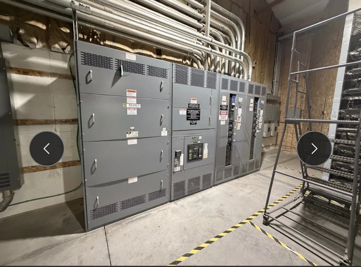
Define the Tomball Project Before Selecting a Switchboard
For a Tomball facility, begin with the distribution problem the new switchboard must solve—not a catalog size or assumed replacement. Identify the source transformer or service, system voltage, phase and wire configuration, available fault current, and the loads the assembly will serve. Note whether the work supports a new building, an expansion, or replacement of existing gear; each can change feeder count, bus arrangement, and connection points. Ask the engineer of record and serving utility to confirm service assumptions rather than carrying forward an unverified value from old drawings. These details help a U.S. manufacturer develop a project-specific configuration and quote. They also reduce late changes that can affect approvals, equipment interfaces, installation planning, and the schedule.
Choose Ratings and Protection for the Actual Electrical System
A switchboard’s voltage, ampacity, short-circuit rating, and protective-device arrangement must be evaluated together against the intended system and applicable project requirements. The available fault current at the installation point can influence the assembly rating and device selection; an existing nameplate alone may not reflect changes to upstream transformers or conductors. Coordinate breaker or fusible-switch types, trip functions, and feeder requirements with the electrical engineer, including selective coordination or arc-energy study needs where specified. For low-voltage switchboard assemblies, UL 891 may be relevant when the particular assembly is appropriately evaluated; it is not a blanket qualification for medium- or high-voltage equipment. Confirm the required standard, evaluation, and labeling for the actual scope before ordering.


Plan Layout, Access, and Future Feeder Capacity
The room and route to the final location can determine whether a proposed lineup is practical. Measure door openings, corridors, turning clearances, overhead obstructions, housekeeping pads, and the working space required by the project’s electrical design. Check where conduits enter and whether cable bending space, rear access, or front-access construction fits the site. In Tomball, projects may involve anything from a compact commercial electrical room to an industrial expansion, so avoid assuming a standard footprint will suit the building. Decide which spare sections or future feeder provisions are genuinely useful; unused space still affects cost and floor area, while insufficient provision can complicate later growth. Share dimensioned room plans and access constraints with the manufacturer before the configuration is finalized.
Make Replacement and Tie-In Requirements Explicit
When new equipment replaces an existing board, document the conditions that shape the transition: verified dimensions, incoming and outgoing conductor locations, bus and breaker information, cable lengths, and any equipment that must remain in service. Photographs and readable nameplate data can help, but field verification by qualified personnel is important when records are incomplete or the installation has changed. Identify shutdown windows, temporary power needs, demolition limits, and the party responsible for disconnecting and reconnecting existing conductors. All electrical work must be planned and performed under appropriate de-energization, lockout, verification, and safety procedures; do not base a schedule on energized installation work. A clear interface scope helps prevent mismatched connections, unexpected rework, and avoidable disruption to the facility.
Build a Quote Package That Supports Engineering Review
A useful request for quotation includes the one-line diagram, load and feeder schedules, project specifications, fault-current information, required protective devices, enclosure or environmental requirements, and drawing or submittal expectations. State the installation location, utility or service assumptions, shipping destination in Tomball, and any receiving restrictions such as limited dock access or delivery-hour windows. Flag required accessories, metering, control wiring, labeling, and coordination with adjacent equipment instead of leaving them implicit. Ask the manufacturer to identify open technical questions and clarify what is included in the proposed assembly. Exact ratings, compatibility, standards, labeling, and availability remain project-specific and should be confirmed in writing. Complete inputs make technical comparison more meaningful and reduce the risk of pricing two materially different scopes as though they were equivalent.
Coordinate Production Timing, Shipping, and Site Readiness
Discuss the required in-service date early, but treat timing as dependent on final approvals, component availability, design changes, and the confirmed scope—not as a guaranteed delivery period. Ask how drawing review, approval turnaround, and changes after release could affect the project sequence. For shipment to Tomball, coordinate the carrier approach, unloading equipment, staging space, weather protection, and a clear route from the drop point to the electrical room. Industrial sites may have controlled access, active truck traffic, or limited laydown area; confirming these conditions before dispatch can prevent a delivery that cannot be safely received. Keep a receiving plan and installation sequence aligned with the contractor’s outage plan. The switchboard should not ship to a site that is unprepared to protect, inspect, and store it.