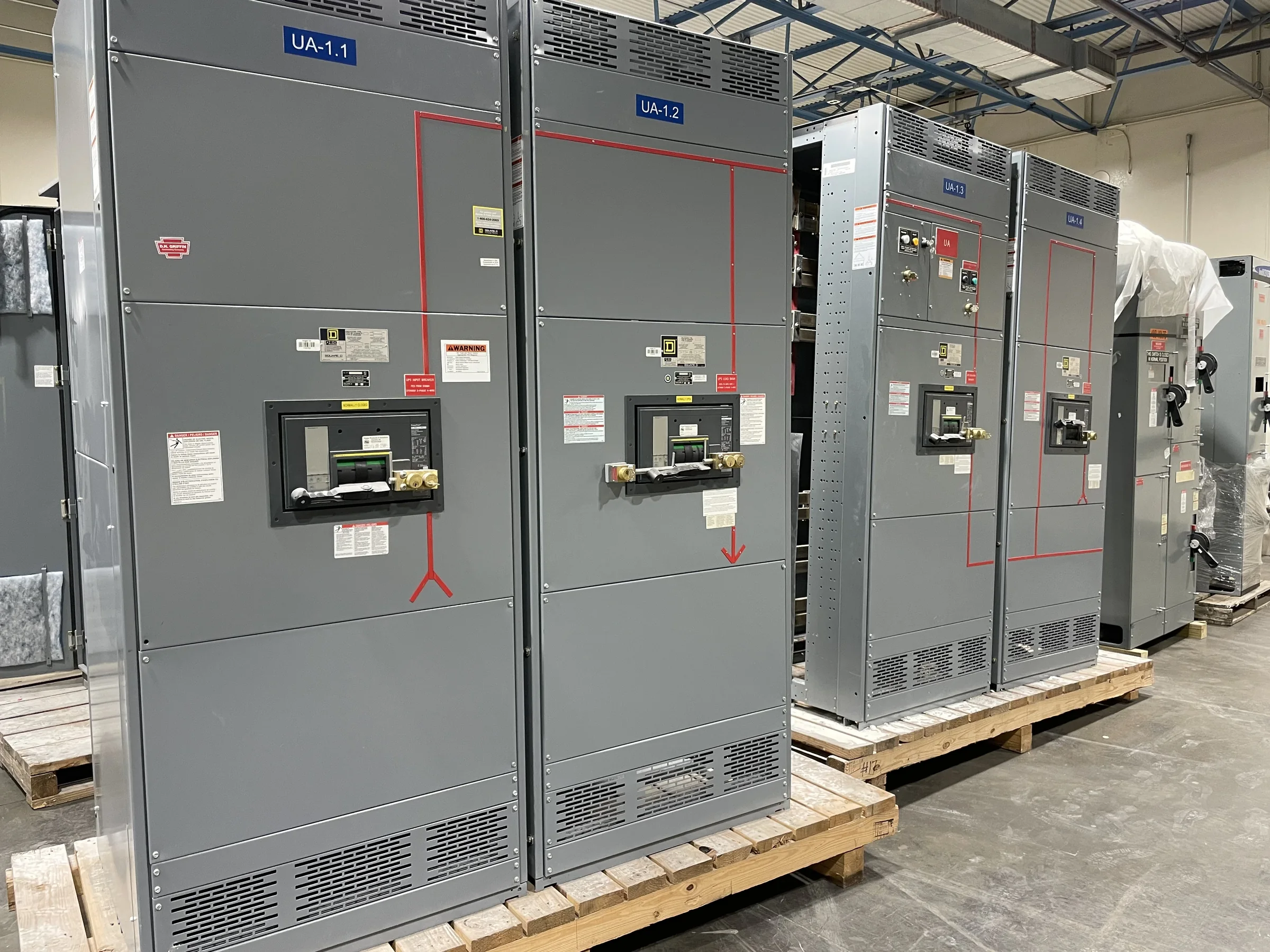
Specify Switchgear Around the Freeport Facility
A sound equipment specification starts with the electrical system the gear must serve, not a catalog label. For a Freeport project, document the service voltage, available fault current, system grounding, source arrangement, connected loads, and the functions required for normal and emergency operation. These inputs shape the assembly configuration, protective-device selection, bus requirements, and compartment layout. Also identify whether the installation is a new service, capacity expansion, or replacement; each can impose different interface and outage constraints. Share one-line diagrams, equipment schedules, and relevant study results with the manufacturer early. If fault-current or coordination data are still being developed, flag that clearly rather than treating assumptions as final. Confirming the design basis before fabrication helps avoid mismatched connections, late engineering changes, and avoidable schedule pressure.
Match the Assembly to the Electrical Application
Switchgear and switchboards are not interchangeable terms for every project, and a product’s application determines which construction and evaluation requirements apply. Low-voltage distribution may call for a switchboard assembly evaluated to UL 891, where appropriate; that reference does not establish a blanket listing for medium- or high-voltage equipment. Specify the system voltage class, continuous-current needs, interrupting requirements, enclosure conditions, metering, and protection functions, then verify the proposed configuration against the project documents and applicable standards. Consider future feeder space and maintainability while reviewing the lineup: a tightly packed initial design may make later expansion or routine access difficult. Exact ratings, standards, compatibility, and labeling depend on the application and final design. Resolve those points with the manufacturer and project engineer before approval.


Plan Replacement Work and Existing-System Interfaces
Replacement projects often hinge on details that are easy to miss in a single-line diagram. Record existing lineup dimensions, bus orientation, cable or conduit entry locations, termination space, control wiring, grounding connections, and the ratings of upstream and downstream equipment. Photograph nameplates and connection areas where site rules permit, and identify any obsolete or undocumented components. A new assembly may require transition sections, revised conductors, structural changes, or protection-setting review; physical resemblance alone does not establish electrical compatibility. For Freeport facilities with continuous processes, define the acceptable outage window and switching boundaries with the facility’s qualified electrical team. All installation and connection work must be planned for a properly de-energized condition, with the site’s safety and verification procedures followed. Early interface checks reduce field rework and outage surprises.
Coordinate Schedule, Submittals, and Design Changes
A realistic procurement schedule includes more than the date equipment is needed on site. Align the required delivery milestone with drawing review, approval cycles, engineering decisions, component availability, production sequencing, and any inspection or witness points the project requires. A U.S. manufacturer can discuss custom configurations and short lead times, but timing depends on the approved scope and current project conditions; obtain a project-specific schedule rather than relying on a general estimate. Establish who can approve drawings and how revisions will be tracked. Changes to breakers, metering, enclosure details, or cable-entry plans after approval can affect cost and timing, so keep one controlled set of requirements. Ask which submittals are included and what information the contractor must provide to release the order for production.
Prepare Freeport Delivery and Receiving Details
Delivery planning in Freeport should account for the destination’s actual access and handling conditions, not just the street address. Confirm the receiving entrance, truck route, gate procedures, turning and overhead clearance, unloading equipment, staging area, and any restrictions on delivery hours with the site team. Coastal and industrial settings can make exposure during staging important: identify whether equipment will be stored indoors, protected from weather, or held before installation, and follow the manufacturer’s handling and storage instructions. Provide shipping contacts and receiving requirements before dispatch, including whether the lineup must arrive in sections or in a particular sequence. Nationwide shipping can support projects in the area, but freight arrangements and delivery timing are job-specific. Coordinating these details early reduces the risk of blocked access, unsuitable unloading, or prolonged outdoor storage.
Review Documentation Before Installation and Startup
Before releasing equipment for installation, compare the approved submittals with the purchase scope, one-line diagram, and site interface requirements. Check lineup arrangement, device functions, ratings, connection points, metering, control provisions, and any specified accessories; resolve discrepancies through documented review rather than field interpretation. Confirm what drawings, manuals, and test or inspection records are included for the ordered assembly, and determine whether the project requires additional documentation or coordination studies. At the Freeport site, verify that foundations, clearances, access paths, conduits, and cable preparations match the approved layout before delivery. Installation, testing, energization, and protective-device settings should be handled by qualified personnel under the project’s safety procedures, with equipment de-energized for applicable work. A complete handoff gives facility staff clearer maintenance references and helps commissioning proceed against an agreed design basis.