Match the Distribution Design to the Facility
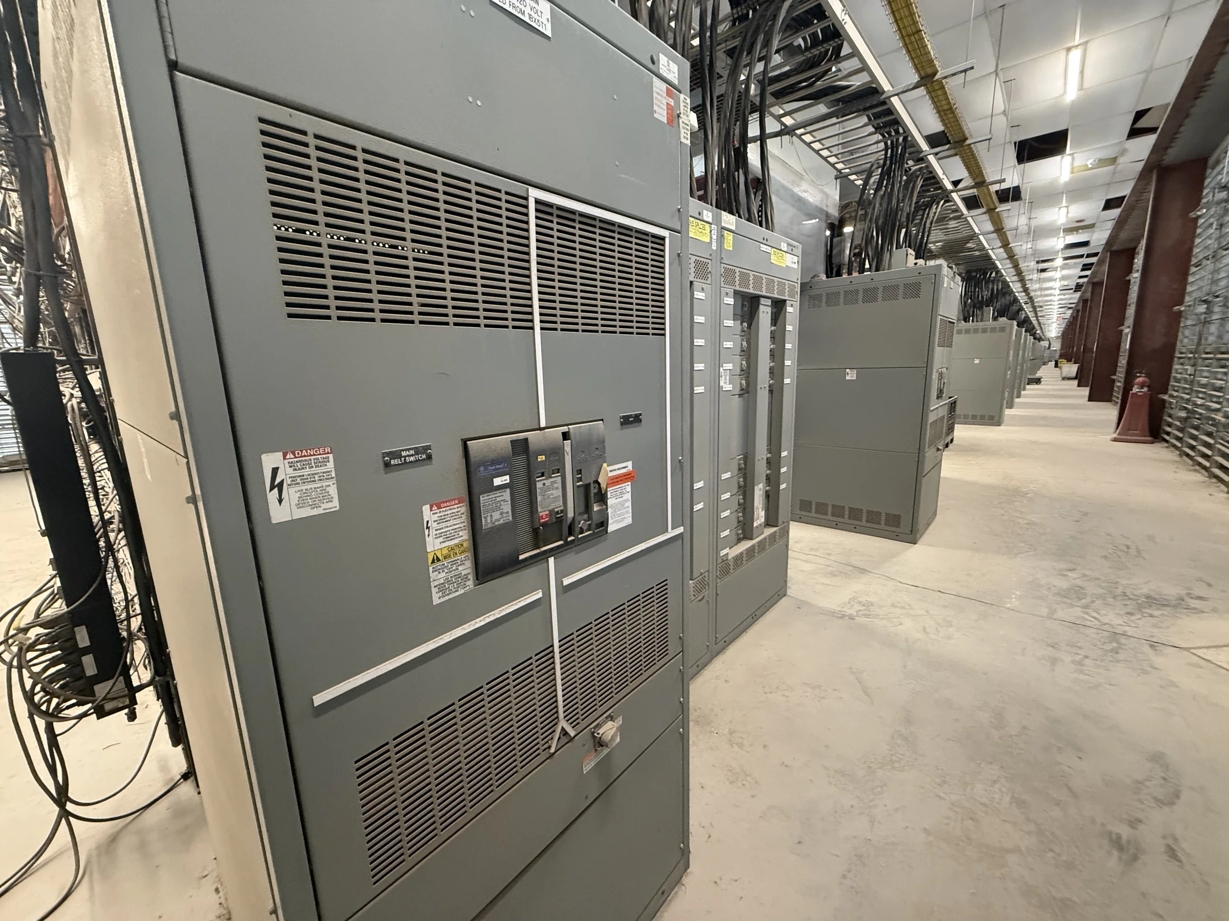
Low-voltage switchgear for an oil and gas facility must fit the electrical system it will serve, not just the available floor space. Start with the one-line diagram, nominal voltage, available fault current, protective-device coordination, and the loads supplied by each section. Compressor drives, pumps, process heaters, lighting, and utility services can place different demands on the distribution lineup. Confirm whether the project needs service entrance equipment, feeder distribution, tie sections, metering, or provisions for future expansion. These decisions affect bus arrangement, compartment layout, interrupting ratings, and interfaces with upstream and downstream equipment. Share current drawings and design criteria when requesting a quote; final ratings and compatibility depend on project review and the applicable evaluation of the specific assembly.
Account for Process-Critical Loads and Continuity
A trip or planned outage can interrupt more than one production function, so identify critical loads and operating priorities before the lineup is specified. Coordinate the switchgear arrangement with the facility’s redundancy strategy, emergency power sources, transfer equipment, and maintenance practices. Where process loads need selective isolation, engineers should define the required feeder groupings and switching sequence in the project documents rather than assume a standard configuration will suit. Consider how operators will identify circuits and understand normal and alternate power paths, especially when equipment serves multiple process areas. Clear circuit designations, metering requirements, and control interfaces reduce ambiguity during commissioning and troubleshooting. The manufacturer needs these requirements early because changes to section layout or controls can affect design coordination and fabrication.


Specify for the Actual Site Environment
Oil and gas sites can expose electrical equipment to dust, moisture, corrosive atmospheres, temperature variation, vibration, and limited indoor space. The relevant conditions differ between a refinery, processing plant, gathering station, and other facility areas, so avoid selecting an enclosure or construction from a broad facility label alone. Provide the intended installation location, indoor or outdoor status, environmental criteria, available clearances, and any project requirements for coatings, heaters, ventilation, or ingress protection. Also identify hazardous-area boundaries; low-voltage switchgear location and installation requirements must be coordinated with the facility’s classified-area design. These details matter because enclosure, access, heat dissipation, and installation interfaces influence suitability. Confirm the final arrangement against site documents and applicable codes before release for manufacture.
Resolve Interfaces Before Approving Drawings
Switchgear is one part of a larger electrical system, and unresolved interfaces can delay installation or create commissioning problems. Provide available information for transformers, generators, utility connections, protective relays, control systems, cable entry, grounding, and external metering. Identify cable sizes and termination preferences where established, along with bus duct or conduit connections and the direction of incoming and outgoing feeders. Review equipment dimensions, lifting provisions, access routes, working clearances, and room layout with the site team. A lineup that fits a schematic may still be difficult to move through a doorway or position around existing piping. Submittal drawings and technical schedules give engineering, procurement, and construction teams an opportunity to verify these interfaces before fabrication details are finalized.
Plan Procurement Around Review and Site Readiness
Project timing depends on more than fabrication duration. Engineering review, approved drawings, component selection, customer comments, site readiness, and transportation coordination all affect the schedule. When discussing timing with a U.S. manufacturer, submit the current specification, quantity, required submittals, requested delivery window, and any approval milestones. Flag long-running project decisions—such as changes to fault-current data, feeder counts, or control requirements—so the team can assess their effect before the design is released. Do not treat a preliminary schedule as a guaranteed delivery date; timing and availability are project-specific and should be confirmed in the quotation and order documents. Early alignment helps procurement plan around required approvals without assuming that unresolved engineering details can be bypassed.
Coordinate Delivery, Installation, and Verification
Nationwide shipping does not remove the need for a site-specific receiving and installation plan. Confirm the delivery address, unloading equipment, receiving hours, access restrictions, laydown area, and whether the route to the electrical room can accommodate the shipment. For remote or congested facilities, coordinate delivery with construction sequencing and the availability of qualified installation personnel; storage conditions also matter if equipment cannot be placed promptly. Before energization, the responsible project team should verify the installed assembly, connections, protective settings, grounding, and documentation against approved project requirements. De-energized work and appropriate safety procedures are essential during installation and maintenance. For applicable low-voltage switchboard assemblies, UL 891 requirements may be relevant, but evaluation and labeling are assembly-specific and must be confirmed for the quoted equipment.