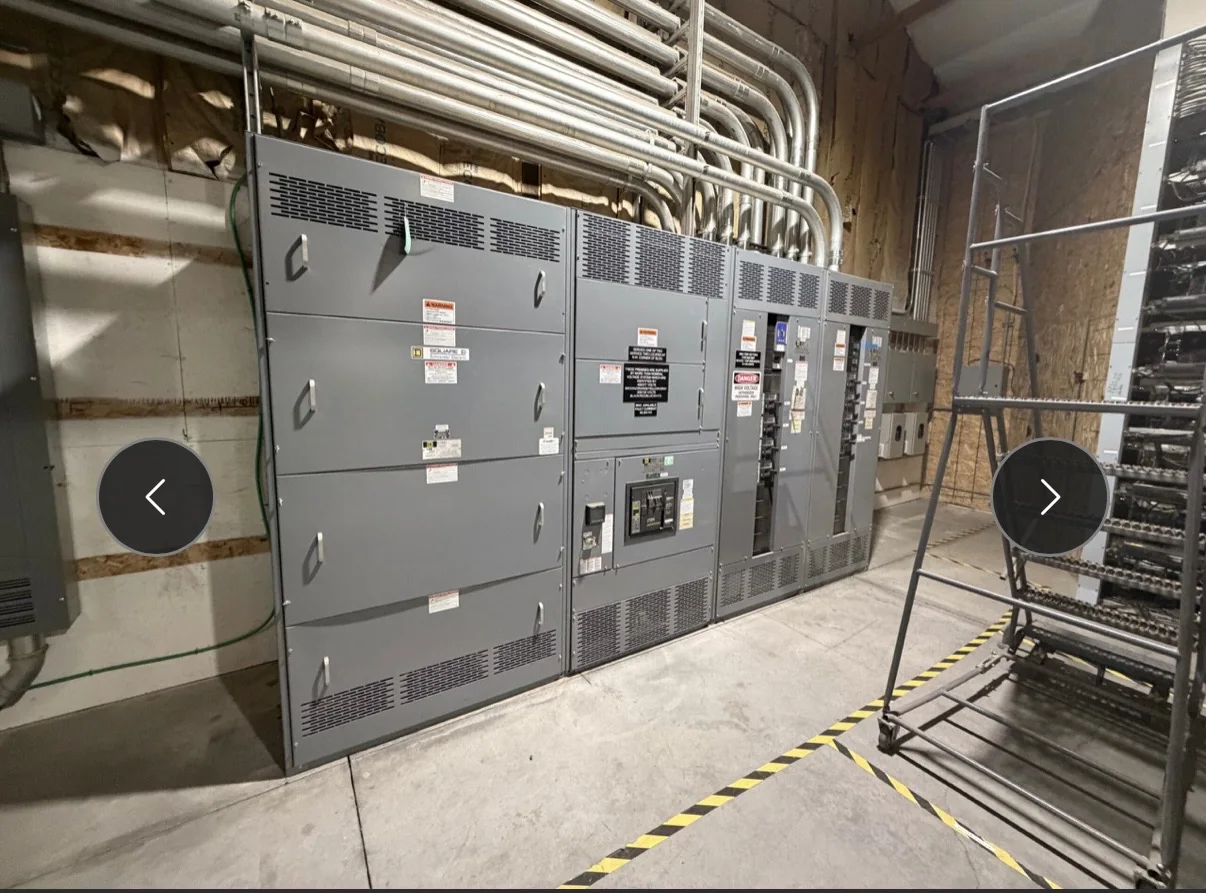
Match the Switchboard to the Petrochemical Load
Petrochemical facilities often distribute power to a changing mix of process equipment, utility systems, and supporting buildings. Begin a low-voltage switchgear specification with the actual one-line diagram and load data, not a presumed standard lineup. Identify incoming sources, tie arrangements, major motor loads, transformer connections, and planned spare capacity. Clarify whether process continuity depends on maintaining particular sections during maintenance or disturbances; that operating requirement can affect lineup arrangement and protective-device coordination. Available fault current, system voltage, frequency, grounding method, and equipment ratings must be established by the project’s qualified electrical team. These details matter because a switchboard that fits the room but does not align with the system study or operating sequence can create costly design revisions. Confirm applicability and ratings during engineering review.
Account for Heat, Corrosion, and Contamination
A petrochemical electrical room may be exposed to elevated ambient temperatures, humidity, salt-bearing air, dust, or chemical contaminants, depending on its location and ventilation. These conditions influence enclosure construction, surface protection, cooling, and maintenance planning; they should be documented rather than left to assumptions. Provide the manufacturer with the room’s environmental design conditions, whether the equipment is indoors or outdoors, nearby process hazards, and any enclosure or access constraints established by the project. Also identify whether the room is classified and share the governing hazardous-area documentation. Low-voltage switchgear is not, by itself, a substitute for equipment specifically required in a classified location. This distinction matters for safe, compliant installation: the electrical design team must determine equipment placement and suitability from the facility’s hazard classification and applicable codes.


Coordinate Protection and Process Continuity
Protective-device selection in a process facility must be reviewed against the available fault current, conductor and equipment ratings, and the facility’s coordination study. Ask the project engineer to identify required trip functions, settings, selective-coordination objectives, and interfaces with upstream and downstream devices. Where emergency power or multiple sources are involved, document the intended transfer and tie logic, including which loads may be shed and who controls restoration. These are project-specific design decisions, not assumptions that can be made from a product category alone. Poorly coordinated protection can interrupt more process loads than necessary, while unclear operating logic can complicate commissioning and response to a fault. Resolve these interfaces during submittal review, and define the required study inputs and acceptance records before equipment release.
Set the Scope Before Requesting a Quote
A useful quotation package includes the latest one-line diagram, preliminary layout, load schedule, electrical characteristics, and the requested equipment scope. Identify whether the request covers a complete new lineup, a replacement assembly, or integration with existing distribution, and state what is excluded. Existing gear can impose limits on room access, cable routing, bus connections, and outage duration; provide verified dimensions and connection information where available. Include the project’s required standards, documentation, inspection expectations, and any requested UL 891 evaluation for an applicable low-voltage switchboard assembly. UL 891 is not a blanket certification for every item or for medium- or high-voltage equipment. Clear inputs help engineers identify open questions early, reduce avoidable quotation changes, and distinguish confirmed project requirements from preferences still under review.
Plan Room Access, Outages, and Installation
A switchgear lineup must be deliverable to its final position, not merely sized for its electrical duty. Check door and corridor clearances, turning space, floor loading, lifting access, available staging, and the route from receiving to the electrical room. Petrochemical sites may also require delivery appointments, badging, vehicle restrictions, escorts, weather planning, or coordination with active construction and process operations. Provide these constraints when discussing schedule and shipping so packaging and delivery assumptions can be reviewed. For replacement work, coordinate the planned outage, existing cable and bus interfaces, demolition sequence, and temporary power requirements with the facility’s authorized team. Installation and connection work must follow approved procedures, with equipment de-energized where required. Early logistics review matters because access conflicts or an unplanned outage can disrupt the project even when the equipment itself is ready.
Review Submittals, Schedule, and Delivery Together
Before releasing a purchase order, align the technical submittal process with the project schedule. Confirm who will review drawings, how comments will be resolved, what information is needed for final manufacture, and which records are required for turnover. Depending on the project, documentation may include approved drawings, bills of material, device data, wiring diagrams, test documentation, and shipping details; the contract should define the actual deliverables. Discuss target dates, shipping destination, receiving hours, and site coordination with the U.S. manufacturer, while treating timing and availability as project-specific rather than guaranteed. American components and custom builds may be considered when developing the scope, but exact component selection and assembly configuration require engineering review. A coordinated submittal and delivery plan helps procurement, engineering, and operations prepare for installation without mistaking an estimate for a commitment.