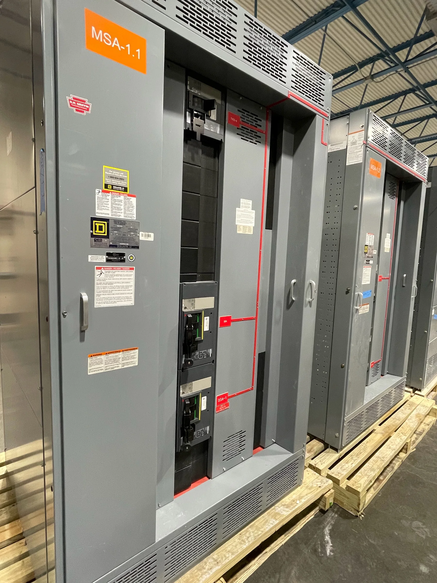
Match the Switchboard to the Utility’s Distribution Duty
Utility facilities use low-voltage switchgear in control buildings, water and wastewater plants, maintenance shops, fleet facilities, substations, and other sites where dependable distribution supports essential operations. Start by defining the source arrangement, nominal voltage, frequency, available fault current, grounding method, and required continuous current; these determine the equipment’s design basis and must be confirmed for the installation. Document normal and alternate sources, transfer requirements, and loads that must remain available during an outage. A switchboard is not a substitute for medium-voltage equipment, and the division between systems should be clear in the one-line diagram. Sharing these operating conditions with the manufacturer early helps align the proposed assembly with the utility’s actual duty rather than a generic equipment description.
Specify Protection, Metering, and Operating Functions
Protection and control requirements should reflect how the utility operates the facility, not just the connected load total. Identify feeder functions, protective-device preferences, metering points, alarm contacts, communications interfaces, and any interlocking or source-transfer logic that belongs in the assembly. Confirm coordination and selective-tripping objectives with the engineer responsible for the system study; device ratings and settings depend on calculated fault conditions and the complete distribution network. If operators need local indication or remote monitoring, define signals, protocols, and responsibility for integration before drawings are finalized. These decisions affect compartment layout, wiring, access, and review time. A clear sequence of operation and device schedule helps the manufacturer prepare equipment that can be evaluated against the project documents and utility standards.


Resolve Ratings, Standards, and Existing-System Interfaces
A procurement package should distinguish required electrical ratings from preferences and identify the governing project specifications and applicable codes. For a low-voltage switchboard assembly, UL 891 may be relevant when the specific assembly is appropriately evaluated; it is not a blanket certification for every product or for medium- or high-voltage equipment. Confirm the requested labeling and evaluation basis for the actual configuration. For replacement work, provide existing equipment nameplates, bus and cable details, breaker information, and available fault-current data where obtainable. Physical or electrical compatibility should never be assumed from a catalog description: bus connections, neutral and ground arrangements, conductor entry, and protective-device characteristics need engineering review. Resolving these interfaces before release reduces redesign risk and helps identify what must be verified in the field.
Plan the Lineup Around the Site and Installation Route
Room conditions and access can constrain the design as much as the electrical load. Provide the equipment room dimensions, ceiling height, door and corridor clearances, housekeeping-pad details, working-space requirements, and the intended cable entry and exit directions. Note environmental conditions such as moisture, dust, temperature, corrosive exposure, or unusual ventilation needs so the project team can define suitable construction. Confirm whether the lineup must pass through existing doors or around operating equipment, and determine how sections will be moved, set, joined, and anchored. Utility sites may have restricted access, security screening, outage windows, or limited laydown space; these are planning inputs, not last-minute shipping notes. Drawings that show the complete route and installation boundaries help expose conflicts before equipment is built.
Build a Complete Submittal and Review Package
Useful procurement documents let engineering, operations, construction, and safety reviewers assess the same design basis. Include the one-line diagram, load schedule, equipment schedule, control and metering requirements, applicable specifications, and known site constraints with the request for quotation. During submittal review, check the proposed arrangement, ratings, device types, dimensions, terminal provisions, wiring information, and any specified markings against the contract documents. Identify deviations explicitly and close them before approval to manufacture; an unrecorded assumption can become a field change or commissioning delay. Define the expected drawing format, review sequence, and responsible approvers at the outset. Also state what documentation is required at turnover, such as final drawings and operating information, subject to the project scope and manufacturer’s confirmed deliverables.
Coordinate Schedule, Delivery, and Replacement Work
Discuss schedule at quotation and confirm it again as design details, approvals, and component availability become known. Custom configurations and project-specific review affect the path from released drawings to shipment, so a stated timing expectation should be treated as project-specific rather than guaranteed. Identify required-on-site dates, receiving hours, unloading equipment, delivery access, and whether shipment needs to be coordinated with a planned outage or phased installation. Nationwide shipping can support utility projects in different regions, but the site team remains responsible for confirming route access, permits where applicable, and safe receiving arrangements. For replacement work, coordinate isolation, de-energization, removal, installation, inspection, and commissioning with qualified personnel under the owner’s procedures. Provide the manufacturer with the final application and delivery details to request a project-specific quotation.