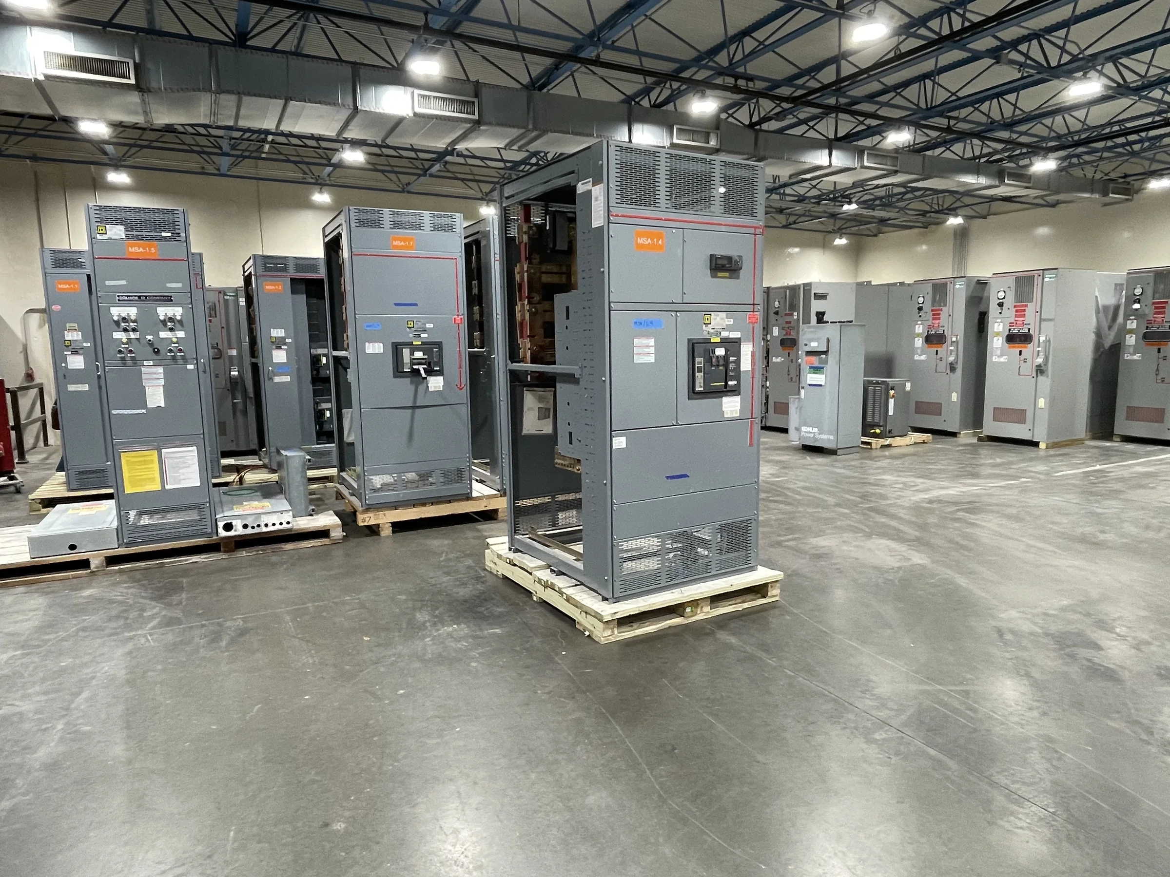
Match Distribution to the Facility’s Process Loads
Wastewater facilities combine loads with different operating patterns: influent and effluent pumps, blowers, mixers, screens, chemical-feed systems, and building services. Their electrical demand may change with process conditions, seasonal flows, or equipment staging, so a switchgear specification should start with the facility’s load study and operating sequence—not a generic equipment schedule. Confirm system voltage, available fault current, service arrangement, required feeder count, and coordination goals with the responsible engineer and utility. Identify critical loads and the consequences of losing each one; that helps the design team assess whether separate sections or sources are appropriate. Motor starting methods and future capacity also affect bus and protective-device decisions. Final ratings, configuration, and protection settings depend on project documents and engineering review.
Plan for Moisture, Corrosion, and Room Conditions
A switchgear lineup in a wastewater building may face humid air, condensation, washdown nearby, corrosive process atmospheres, or temperature changes that challenge enclosure integrity and long-term reliability. Document the actual installation environment, including room ventilation, drainage, cleaning practices, chemical exposure, and whether equipment is indoors or outdoors. These details help the manufacturer and engineer evaluate enclosure construction, finish, access, and any environmental provisions suitable for the application. Do not assume that a nominal indoor enclosure is appropriate simply because the gear sits under a roof. Room layout matters, too: allow for working clearances, cable entry, door swing, heat dissipation, and removal paths. The project team should resolve these constraints before drawings are approved, since late changes can affect both equipment arrangement and site readiness.


Coordinate Protection With Pumps and Backup Power
Pump and blower circuits can create demanding starting conditions, while utility interruptions may require generators or other backup sources to support essential treatment processes. The switchgear design should reflect the facility’s one-line diagram, motor-control approach, transfer scheme, and intended operating modes. Protection must be coordinated with upstream service equipment and downstream motor controllers so that a fault is isolated appropriately without unnecessarily interrupting unrelated process loads. Where standby power is involved, document source ratings, transition requirements, interlocks, and the loads intended to operate during an outage. These are engineering decisions, not assumptions to settle from a product description. Provide available fault-current data and current equipment information early; incomplete inputs can delay review or lead to revisions when the project team checks compatibility and coordination.
Specify Drawings, Interfaces, and Replacement Constraints
For a new plant or an upgrade, procurement documents should make the switchgear’s boundaries clear. Useful submittal inputs include the one-line diagram, load and feeder schedules, control and metering needs, cable-entry preferences, room plans, and applicable project standards. For replacement work, add verified dimensions, existing bus and conductor information, upstream and downstream equipment details, and photographs or drawings that show access routes. A replacement lineup may need to fit a room designed around legacy gear, yet dimensional similarity alone does not establish electrical compatibility. The engineer should review connections, protection, grounding, and system conditions before approving a retrofit approach. Agree on drawing review stages and required record documents with the supplier, so purchasing, engineering, and field teams can identify conflicts before equipment is released for manufacture.
Discuss Schedule and Delivery Before Release
Wastewater projects often coordinate electrical work with process outages, construction phases, and commissioning milestones. Discuss the requested ship window, approval sequence, change-control process, and delivery assumptions with the manufacturer before purchase, then confirm them against the project schedule as drawings develop. Short lead times may be available, but timing depends on the approved configuration, component availability, engineering inputs, and production conditions; it should not be treated as a blanket guarantee. Nationwide shipping can support projects across the United States, yet the receiving plan still needs attention. Confirm truck access, unloading equipment, delivery hours, staging space, and whether the site can protect equipment from moisture and construction debris. A missed delivery window or unsuitable unloading route can disrupt installation even when the lineup is ready.
Prepare the Site for Safe Installation and Commissioning
A delivered assembly is only one part of a successful wastewater-facility upgrade. Before installation, the project team should verify the foundation and anchorage requirements against approved drawings, confirm conduit and cable locations, and ensure the electrical room is clean, accessible, and ready for equipment. Plan de-energized work, lockout/tagout, utility coordination, and outage approvals through qualified personnel under the facility’s safety procedures. Commissioning planning should identify responsibilities for inspection, testing, protective-device settings, control interfaces, and turnover records; acceptance criteria must come from the project specifications and responsible engineer. Keep approved drawings and equipment documentation available to operations staff, who may need them for maintenance and future expansions. Clear handoffs reduce startup surprises and help protect treatment continuity during the transition.