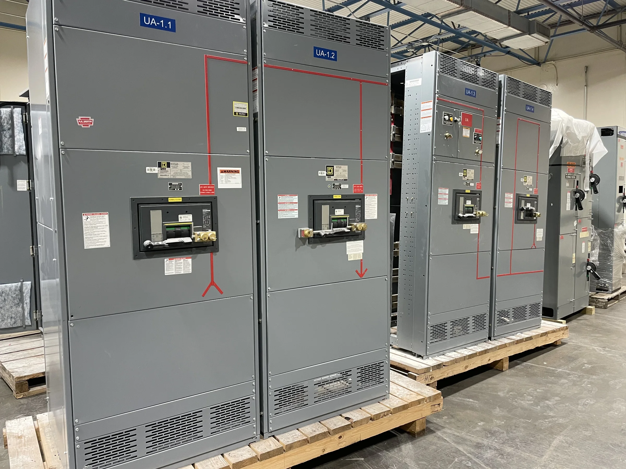
Define the Beaumont Distribution Duty
Start a Beaumont low-voltage switchgear specification with the electrical duty the assembly must perform, not a preferred catalog label. Confirm system voltage, phase and frequency, available fault current, main and feeder requirements, grounding arrangement, and the intended service environment with the project engineer. These inputs shape bus ratings, protective-device selection, compartment layout, and the assembly’s evaluated configuration. A switchboard designed for a commercial service entrance may not suit an industrial process lineup, even when both are described as low voltage. Identify whether the work is new construction, capacity expansion, or replacement, and document what existing equipment must remain connected. Those distinctions matter because interfaces, outage planning, and physical fit can constrain the design as much as electrical ratings.
Coordinate Protection and Connected Equipment
Protection should be coordinated with the equipment and operating sequence downstream, rather than chosen in isolation. Share the latest one-line diagram, load information, transformer data, and available fault-current study when requesting a quotation; incomplete or outdated inputs can lead to revisions after review. Identify motor loads, sensitive electronic equipment, standby sources, and any required selective coordination or arc-energy reduction objectives. The engineer of record must establish project-specific protection criteria and verify the final design. For a replacement lineup, record existing breaker types and settings where available, but do not assume a new assembly will accept old devices or duplicate their performance. Confirm compatibility and replacement scope before procurement. A clear responsibility matrix for studies, settings, and field verification helps prevent gaps between manufacturer, contractor, and design team.


Check the Beaumont Site Before Finalizing Layout
In Beaumont, site review should account for the actual building and route to the electrical room—not just the room’s nominal dimensions. Measure clear working space, door openings, overhead obstructions, floor transitions, turning areas, and the path from unloading point to final position. Gulf Coast heat and humidity can influence room ventilation, condensation control, and enclosure decisions, particularly where equipment is exposed during construction or installed in a less-controlled space. These conditions do not determine a rating by themselves; the project team must specify the environment and confirm the appropriate equipment. Check floor loading and anchorage requirements with the responsible structural professional. A dimensioned room plan and delivery-path photos can reveal access conflicts early, when section arrangement or shipping configuration may still be adjusted.
Specify the Assembly and Its Documentation
A useful purchase package connects the electrical design to the equipment that will arrive. Provide the one-line diagram, project specifications, panel schedules, enclosure and environmental requirements, control schematics, metering needs, and any approved equipment standards. Call out required dimensions, cable entry direction, conductor space, labeling conventions, and integration points for building controls or communications. If a UL 891 switchboard assembly is required, state that requirement clearly and confirm the specific assembly’s evaluation and labeling during submittal review; UL 891 should not be treated as a blanket certification for every low-voltage product or for medium- and high-voltage gear. Request drawings and applicable product documentation for review before release. Resolving discrepancies at this stage helps reduce field modifications, coordination delays, and uncertainty about acceptance responsibilities.
Plan Timing Around Reviews and Outages
Discuss timing with the manufacturer while the design is still being developed, and distinguish quotation, drawing review, approval, fabrication, and shipment milestones. Custom dimensions, device selections, submittal revisions, and unresolved interface questions can affect the schedule; a quoted timeframe should be confirmed for the final approved scope rather than assumed to apply unchanged. Beaumont projects involving operating facilities should align equipment changeover with the owner’s outage windows, contractor availability, commissioning plan, and any temporary distribution strategy. Establish who reviews drawings and how quickly comments are returned, since an approval hold can shift downstream work. For replacement projects, verify field dimensions and connection information before releasing the order. A realistic schedule is built from documented scope and review responsibilities, not from a general promise of fast delivery.
Coordinate Freight, Receiving, and Turnover
Nationwide shipping can support a Beaumont project, but delivery planning remains a site-specific task. Confirm the receiving location, unloading equipment, access restrictions, delivery-hour rules, and who will inspect and take custody of the shipment. Coordinate section weights and handling information from approved documents with the rigging and installation teams; do not infer lifting or placement methods from appearance. Protect equipment from construction dust, moisture, and impact during staging, and follow the manufacturer’s storage instructions if installation cannot proceed promptly. Before energization, qualified personnel should complete the required installation checks, verify settings and connections, and follow the project’s approved commissioning and safety procedures. Keep final drawings, equipment schedules, test documentation, and operating information with facility records. A complete handoff helps maintenance teams identify what was installed and manage it responsibly.