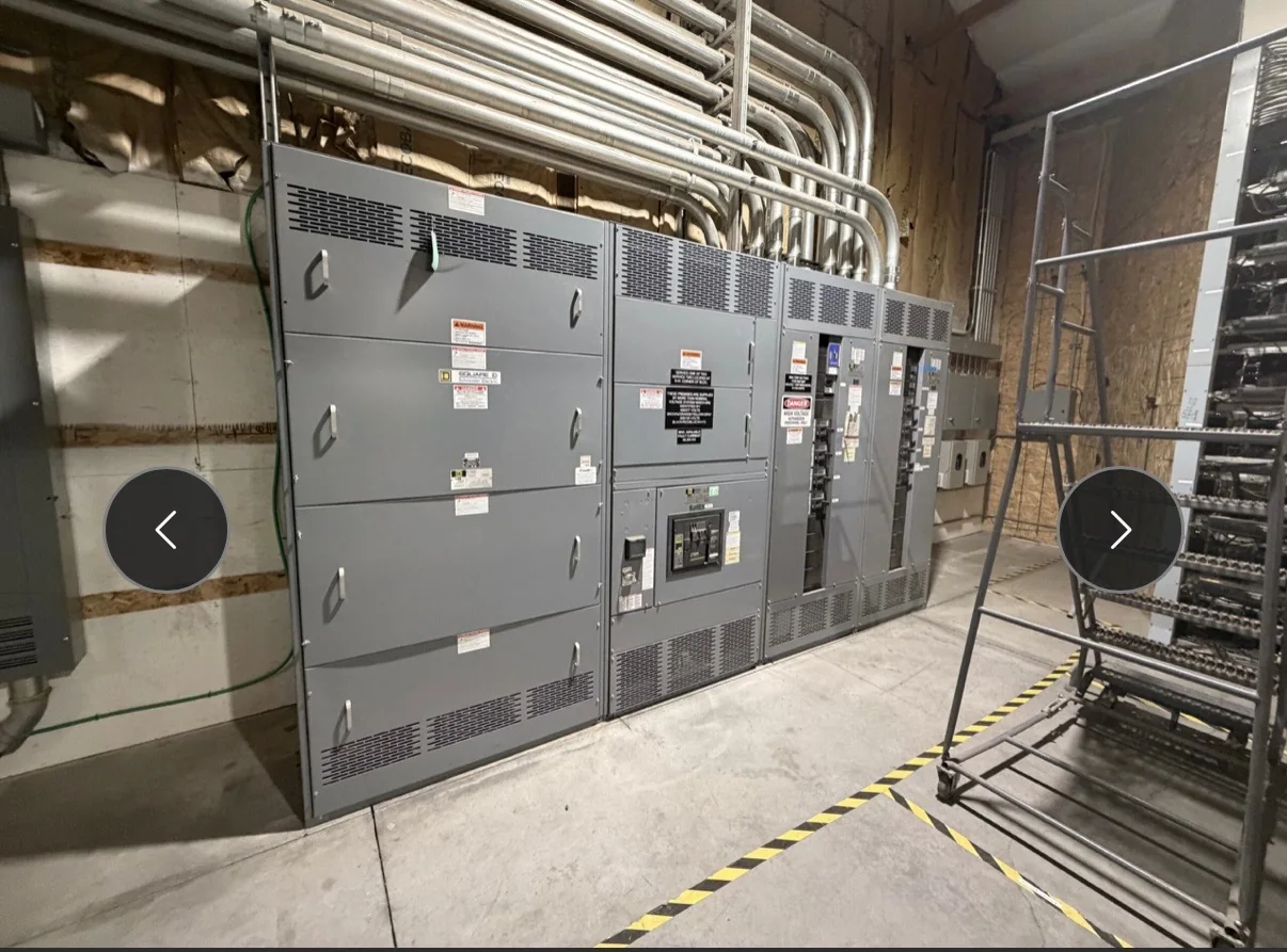
Map the Plant’s Distribution Architecture
Manufacturing plants often combine utility service, on-site generation, transformers, and multiple production areas, so medium-voltage switchgear should be specified as part of the complete distribution path—not as an isolated equipment order. Start with the one-line diagram and identify normal and alternate sources, tie points, transformer connections, major loads, and the intended operating arrangement. Clarify whether equipment will serve a new process line, replace an existing lineup, or support a broader expansion; each case can impose different interface and outage constraints. Provide available system voltage, grounding method, fault-current information, and protective-device coordination requirements for engineering review. These inputs affect equipment configuration and evaluation. Confirming them early helps the manufacturer identify missing information before drawings advance and reduces the risk of a lineup that cannot integrate with the plant’s actual system.
Specify Protection Around Process Consequences
Protection decisions in a manufacturing facility must account for both electrical conditions and the consequences of losing a process. A fault on a shared bus can interrupt several production areas, while a protective setting that is too slow may expose equipment to unnecessary damage. The plant’s engineer or coordination consultant should define the required protection philosophy, relay functions, trip logic, metering, and interfaces with upstream and downstream devices. Supply current and voltage transformer requirements, available fault data, and relevant coordination studies where available; assumptions should be clearly marked for verification. Consider how alarms and status points reach the control system, and identify any communications protocol or monitoring interface required by the project. Final device selection, settings, and application depend on system studies, equipment compatibility, and review by qualified engineering personnel.


Plan the Lineup for Real Site Conditions
A sound electrical design can still become difficult to install if the lineup does not fit the room, cable route, or access path. Before requesting a build, document room dimensions, ceiling height, floor conditions, clearances, door openings, equipment access, cable trench or conduit entry, and the intended location of incoming and outgoing connections. Verify whether the existing building can accept the proposed arrangement and whether equipment must pass through restricted corridors, loading areas, or production spaces. Manufacturing environments may also involve dust, heat, vibration, washdown, or corrosive exposure; describe actual conditions rather than relying on a generic enclosure assumption. These details affect layout, construction, and handling. The project team should confirm applicable code requirements and installation clearances with its engineer and authority having jurisdiction before approving final drawings.
Coordinate Replacement Work and Outage Windows
Replacing medium-voltage equipment in an operating plant calls for disciplined outage planning because production schedules, utility coordination, and safe access all influence the installation sequence. Identify the existing lineup’s manufacturer and model if known, its nameplate data, bus arrangement, connection points, and available drawings. Photographs and field measurements can help explain conditions, but they do not replace a qualified site assessment. State which loads can be interrupted, what backup sources exist, and whether temporary operating arrangements are being considered; those choices require engineering and operational approval. Agree on drawing review, submittal milestones, site readiness responsibilities, and the target outage window before committing to a schedule. Work on electrical equipment must follow applicable safety procedures, including de-energization and verification by qualified personnel. Never treat schedule pressure as a reason to bypass safe isolation.
Build a Complete, Reviewable Procurement Package
A clear request for quotation gives procurement, engineering, and the manufacturer a common basis for evaluating a new switchgear package. Include the one-line diagram, specifications, equipment schedule, control schematics or functional requirements, site layout, applicable standards, and known interface details. Identify required relays, meters, communications, auxiliary power, cable termination provisions, and any accessories, while distinguishing firm requirements from preferences or open questions. Ask for a scope statement that shows what is included, what requires customer or contractor coordination, and which assumptions still need confirmation. Review proposed drawings for electrical interfaces, dimensions, access, and control functions—not just the equipment description. A U.S. manufacturer can discuss a custom build using American components, but component selection, configuration, standards, and any required evaluation remain specific to the project and must be documented before release.
Align Timing, Delivery, and Turnover Documents
Project timing depends on approved design information, component availability, fabrication scope, review cycles, and shipping coordination, so request a project-specific schedule rather than assuming a standard delivery period. Identify the date equipment is needed on site, the planned receiving location, unloading responsibility, storage conditions, and any limits on truck access or delivery hours. Nationwide shipping is an available offering, but the plant team should confirm route, handling, packaging, and site-readiness details for its shipment. Before purchase, agree which submittals and turnover records are needed, such as approved drawings, operating and maintenance documentation, and applicable test or evaluation records. UL 891 applies to appropriately evaluated low-voltage switchboard assemblies; it is not a blanket certification for medium-voltage switchgear. Confirm the exact equipment scope, applicable standards, labeling expectations, schedule, and delivery terms in the project documents.