Match the Switchgear to the Facility’s Distribution Plan
Oil and gas facilities can include well pads, gathering and compression stations, processing plants, refineries, terminals, and pipeline infrastructure. Each setting has a different power-system layout, so begin with the one-line diagram and the role of the medium-voltage lineup: incoming service, feeder distribution, motor loads, tie breakers, or a combination. Document system voltage, available fault current, grounding method, load profiles, protection scheme, and the normal and alternate operating arrangements. These inputs shape equipment selection and help reveal whether the proposed lineup fits the wider system. Include future feeders and planned expansions in the review; spare space and provisions must be defined rather than assumed. Final ratings, configuration, and standards depend on project engineering and utility requirements.
Account for Process Loads, Protection, and Continuity
Large motors, transformers, variable-frequency drives, and process equipment can place very different demands on a switchgear lineup. Share motor-starting methods, load sequence, duty cycles, and any expected operating modes with the engineering team so the protection and switching approach can be coordinated with the facility design. A compressor station, for example, may need a clear operating plan for a feeder outage while critical loads remain supplied; the lineup alone cannot guarantee process continuity. Protection settings and coordination should be reviewed with the system study and the devices upstream and downstream. Specify control power, metering, communications, interlocks, and remote-operation interfaces where required. Confirm responsibility for studies, relay settings, and integration early, because unclear scope can delay review and commissioning.


Specify Environmental and Installation Conditions
Site conditions influence enclosure, construction, access, and maintenance planning. Identify whether equipment will be installed indoors or outdoors, and describe ambient temperature range, elevation, humidity, dust, corrosive exposure, vibration, and any hazardous-area boundaries relevant to the installation. Do not assume switchgear is suitable for a classified location simply because it serves an oil and gas process; equipment placement and area classification require project-specific engineering. For remote or exposed sites, evaluate shelter requirements, ventilation, condensation control, and protection from weather or industrial contaminants. Provide the room layout, floor and anchorage details, cable-entry direction, working clearances, and equipment access route. These details matter because a lineup that meets electrical needs can still be difficult to install or service if the building and delivery path are not considered.
Resolve Interfaces Before Releasing the Build
A useful quotation package gives the manufacturer enough information to identify open engineering decisions, not just a requested voltage and price. Include the one-line diagram, equipment schedule, preliminary layout, technical specification, applicable project standards, and known utility requirements. Mark requested breaker arrangements, bus configuration, instrument transformers, relays, metering, control circuits, and communication protocols, while identifying items still under review. Confirm which party supplies cable terminations, protection studies, external control wiring, and commissioning support; these boundaries vary by project and should not be presumed. For replacement work, provide existing equipment details, available dimensions, cable locations, and photographs or drawings when available. Early interface review can uncover mismatched assumptions before fabrication documents are approved, reducing avoidable revisions and helping procurement compare technically equivalent proposals.
Plan Schedule Around Engineering, Approvals, and Site Readiness
A short manufacturing lead time is useful only when the project is ready to support the required reviews and decisions. Discuss the target dates for submittal review, drawing approval, release to production, requested shipment, and site installation, then confirm what information is needed at each stage. Review cycles, custom features, component availability, and design changes can affect timing, so no delivery date should be treated as assured until project details and availability are confirmed. On oil and gas projects, coordinate the equipment schedule with outage windows, construction sequencing, shelter completion, and the arrival of connecting transformers or cable systems. Assign decision-makers for technical comments and document revisions. This coordination helps avoid a lineup arriving before the room, access route, or receiving team is prepared.
Coordinate Shipping, Receiving, and Project Records
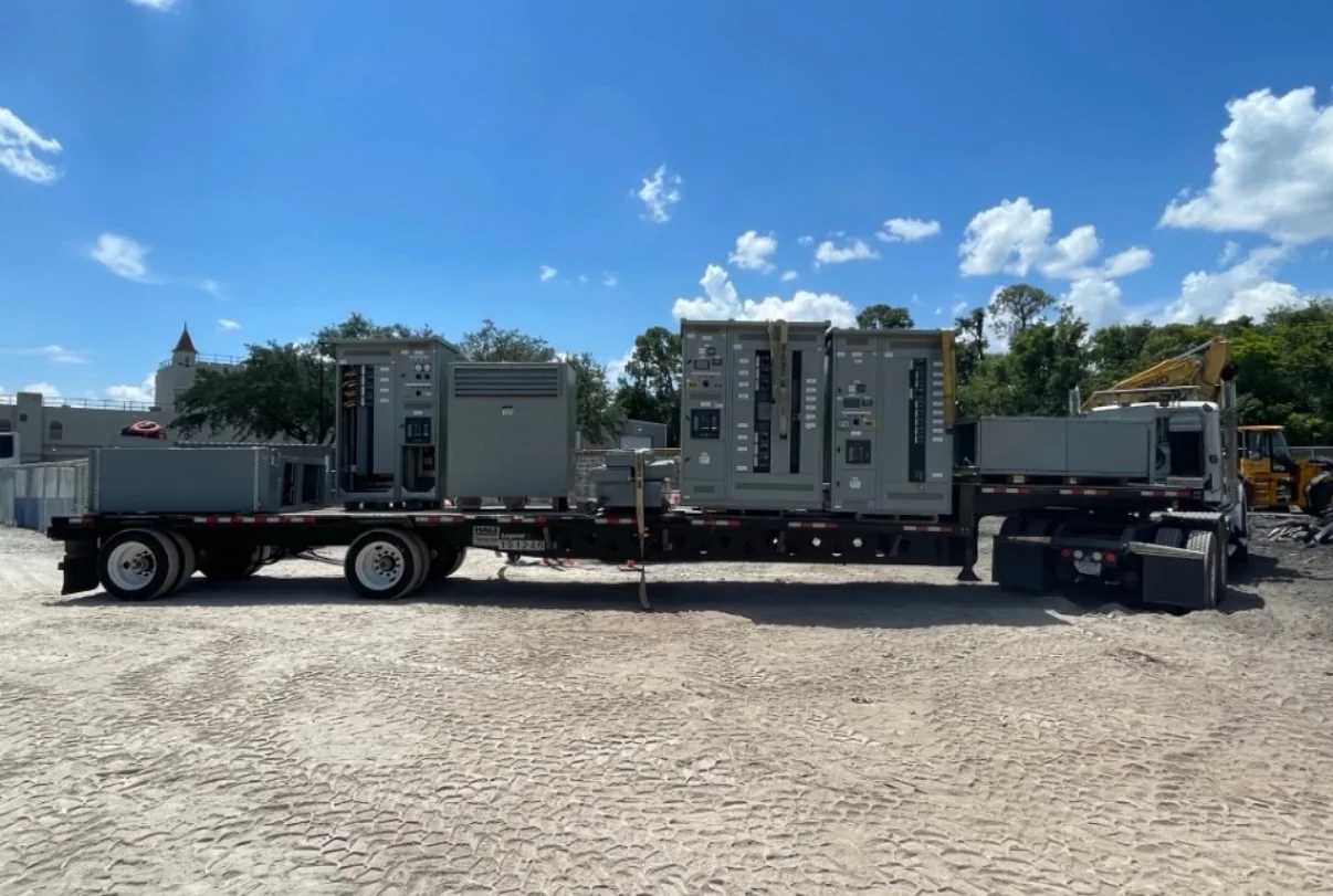
Nationwide shipping can support projects at remote facilities, but delivery planning starts with the site’s physical constraints. Confirm the receiving address, unloading equipment, truck access, turning space, delivery-hour limits, security or gate procedures, and whether the shipment must be staged or transferred to a smaller vehicle. Share packaging, handling, and storage requirements with the site team, especially when the electrical room is not ready at arrival. The approved submittal set should define the supplied configuration and interfaces; retain current drawings, equipment schedules, operating and maintenance information, and applicable test or inspection documentation with the project records. Ask which documents are included and when they are furnished. For appropriately evaluated low-voltage switchboard assemblies, UL 891 may be relevant; it is not a blanket certification for medium-voltage equipment.