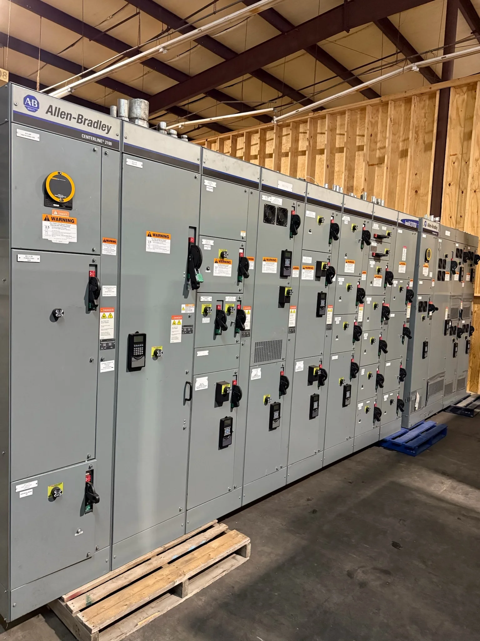
Match the Switchgear to the Plant’s Distribution Scheme
Petrochemical facilities often connect process units, utilities, substations and off-site systems through a distribution network that must remain understandable during normal operation and planned outages. Define the intended voltage, frequency, available fault current, bus arrangement, feeder count and source configuration before requesting a quotation. Clarify whether the lineup serves motors, transformers, incoming utility power, tie connections or a combination, because each duty affects equipment selection and coordination with downstream devices. Identify operating modes that could change fault levels, such as parallel sources or standby generation, and provide the applicable study assumptions. These inputs help the manufacturer develop equipment around the project rather than a generic lineup. Final ratings, protective-device selections and standards applicability require project-specific engineering review.
Account for Corrosive, Hot and Hazardous Areas
Process environments can expose electrical equipment to chemical vapors, salt-laden air, dust, high ambient temperatures or washdown practices. These conditions matter because enclosures, finishes, ventilation and component materials must suit the actual installation, not merely the facility’s general description. Identify the proposed indoor or outdoor location, nearby chemical processes, temperature range, elevation, humidity, ingress concerns and any hazardous-area boundaries. Medium-voltage switchgear is not automatically suitable for installation inside a classified area; confirm the area classification and equipment location with the project’s electrical and safety teams. Also consider whether cooling-air paths could draw in contaminants or whether maintenance access exposes workers to process hazards. Submit site conditions early so enclosure and arrangement decisions can be evaluated before drawings are approved.


Coordinate Protection, Interlocking and Plant Controls
A switchgear lineup must work with the protection and operating philosophy of the wider plant. Provide available short-circuit and coordination studies, relay requirements, trip and close circuit details, control-power sources, communications protocols and interfaces to the plant control system. Explain the intended interlocking logic for breakers, bus ties, grounding devices and transfer schemes; ambiguous sequences can create commissioning delays or unsafe operating conditions. Where process continuity is critical, define which loads may be shed, which sources are preferred and how abnormal conditions should be alarmed. Confirm whether the project requires specific relay functions, metering points, event records or remote indications. These choices affect wiring, terminal blocks, testing and documentation. Final settings and logic should be reviewed by qualified project engineers against the approved system studies.
Plan Layout, Access and Installation Before Release
Medium-voltage equipment can be difficult to place in congested substations, process buildings and brownfield electrical rooms. Before approving a lineup, compare its proposed footprint and section arrangement with room dimensions, door openings, floor elevations, cable trenches, overhead obstructions and required working clearances. Confirm cable entry and exit directions, bending space, bus duct or conduit interfaces, lifting access and the route from the receiving point to the final location. Existing foundations and cable positions may not match a replacement arrangement, so field verification can prevent costly site rework. Consider future feeder additions only when the electrical scheme, room space and bus design support them. Share marked-up plans, photographs and interface drawings with the manufacturer, and resolve dimensional conflicts during drawing review rather than at delivery.
Build Procurement Around Complete Project Information
A useful quotation package gives the manufacturer enough detail to identify scope boundaries and flag unresolved decisions. Include the one-line diagram, equipment schedule, technical specification, load and feeder data, fault-current basis, protection requirements, site conditions, layout drawings and applicable project standards. State the requested scope for breakers, relays, metering, control wiring, accessories, spare parts, installation support and commissioning documentation. Identify exceptions, owner-furnished interfaces and approval milestones so competing proposals can be compared on equivalent terms. If information is preliminary, label assumptions and open items instead of treating them as settled requirements. Review proposed deviations carefully: a difference in bus arrangement, enclosure construction or control interface can affect safety, operations and downstream coordination. Confirm final compliance and product availability for the specific project.
Discuss Schedule, Shipping and Turnover Requirements Early
Project timing depends on approved scope, engineering decisions, component availability, drawing review, manufacturing sequence and required testing; a short lead-time offering is not a guarantee for every configuration. Share the required on-site date, outage window, approval deadlines and any phased construction plan when discussing procurement. Confirm what schedule milestones are included in the proposal and identify decisions that could affect them, including late relay selections or changing cable interfaces. Petrochemical sites may require controlled receiving hours, advance delivery notices, designated carriers, vehicle restrictions or special unloading arrangements. Coordinate shipping dimensions, weights, packaging, laydown space and lifting resources with site logistics before release. Agree on turnover documents such as approved drawings, wiring diagrams, bills of material, test records and operating information, with exact deliverables confirmed in the project scope.