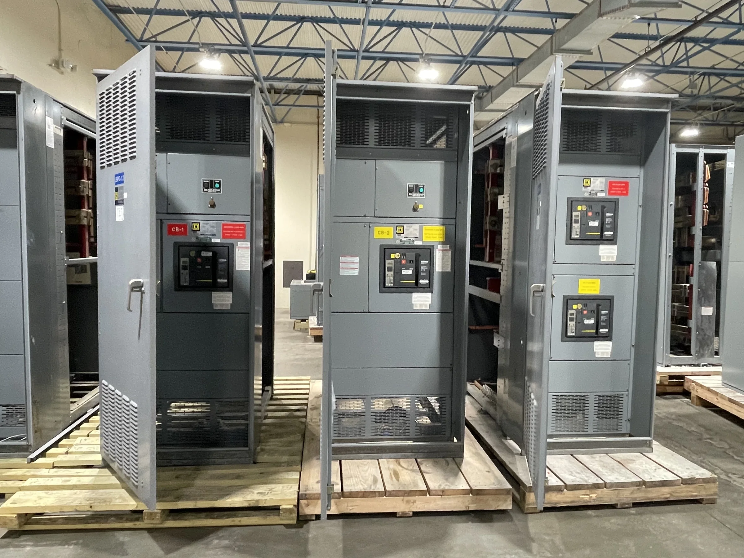
Coordinate Distribution With the Port’s Operating Plan
A port distribution upgrade has to fit around cargo movement, vessel calls, and the availability of existing electrical systems. Before specifying medium-voltage switchgear, identify which loads serve cranes, refrigerated containers, pumps, lighting, workshops, and terminal buildings, then map the proposed equipment to the relevant feeders and operating priorities. This helps engineers distinguish essential services from loads that can be interrupted during a planned changeover. Ask the project team to document the normal and alternate supply arrangements, expected load growth, and any required tie or transfer functions. These decisions affect lineup configuration, protection coordination, and outage planning. Because terminal operations may run across multiple shifts, the procurement schedule should account for review cycles and commissioning windows—not just equipment fabrication.
Define Ratings and Protection From Verified System Data
Medium-voltage ratings and protective functions must come from the facility’s actual system conditions, not from a generic port application. Provide the manufacturer with available one-line diagrams, nominal system voltage, grounding method, fault-current study, relay requirements, and the source and transformer information needed for coordination. Confirm whether the scope includes incoming, feeder, tie, metering, or other sections, and identify how each circuit is expected to operate. Fault duty, insulation level, continuous current, and interrupting requirements are project-specific; a qualified engineering team must verify them against the system and applicable standards. This matters particularly where utility service, on-site generation, or multiple transformers interact, since incorrect assumptions can undermine protection selectivity or make proposed equipment incompatible with the installation.


Account for Salt Air, Moisture, and Terminal Conditions
Marine terminals expose electrical equipment to conditions that may differ substantially from a dry indoor industrial room. Salt-laden air, windblown dust, condensation, temperature variation, and water intrusion can influence enclosure selection, materials, ventilation, heaters, and maintenance planning. Describe the proposed installation location precisely: indoor or outdoor, distance from the shoreline where relevant, room climate control, expected ambient conditions, and any washdown or flood exposure. Do not assume that an enclosure described as weather-resistant is suitable for every coastal environment; required construction and environmental ratings must be established for the site and evaluated configuration. Clearances and access routes matter as well: switchgear doors, cable terminations, lifting provisions, and service space need to work within the actual building or equipment pad, not merely fit on a drawing.
Plan Interfaces With Cranes, Drives, and Existing Feeders
Port loads often include large motors and variable-frequency drives, but the switchgear specification should distinguish what the equipment is required to control from what is supplied elsewhere. Share motor lists, starting methods, drive details, transformer data, cable information, and operating sequences when they are available. These interfaces inform feeder protection, metering, control wiring, and coordination with downstream equipment. Confirm whether the project requires provisions for remote status or control, communications protocols, interlocks, or integration with a supervisory system; compatibility cannot be assumed without reviewing the devices and project documents. For crane or shore-side systems, document the boundary between the terminal distribution scope and specialized equipment packages. A clear responsibility matrix reduces omissions, avoids conflicting assumptions about control power and signals, and helps the commissioning team test the complete system.
Prepare a Procurement Package That Supports Review
A useful request for quotation gives the U.S. manufacturer enough information to assess the proposed build without treating an incomplete drawing as a final design. Include the latest one-line diagram, equipment location and layout, cable entry and exit requirements, system studies, preferred component information, and applicable project specifications. Identify required submittals, drawing review milestones, inspection or testing expectations, spare parts, and documentation for operations and maintenance. If a low-voltage switchboard is also part of the project, determine whether UL 891 applies to that appropriately evaluated assembly; it is not a blanket certification for medium-voltage or high-voltage equipment. Mark uncertain items as open questions rather than silently fixing assumptions. This improves technical review and makes quotations easier to compare on configuration, scope, exclusions, and schedule.
Align Fabrication and Delivery With Site Readiness
Short lead times may be available, but an achievable schedule depends on the approved scope, component availability, drawing turnaround, and manufacturing requirements for the specific order. Discuss target dates early and identify when the terminal can receive, store, and install the equipment. Delivery coordination should account for port access procedures, security requirements, receiving hours, crane or forklift capacity, route restrictions, unloading responsibility, and protection from weather during staging. Confirm shipment dimensions and handling provisions against the site’s gates, roads, laydown area, and final equipment-room entrance before release. A delivery date alone does not establish readiness: foundations, grounding, cable routes, clearances, and installation labor should also be coordinated. For replacement work, plan the approved outage and de-energized installation sequence with the facility’s qualified electrical professionals.