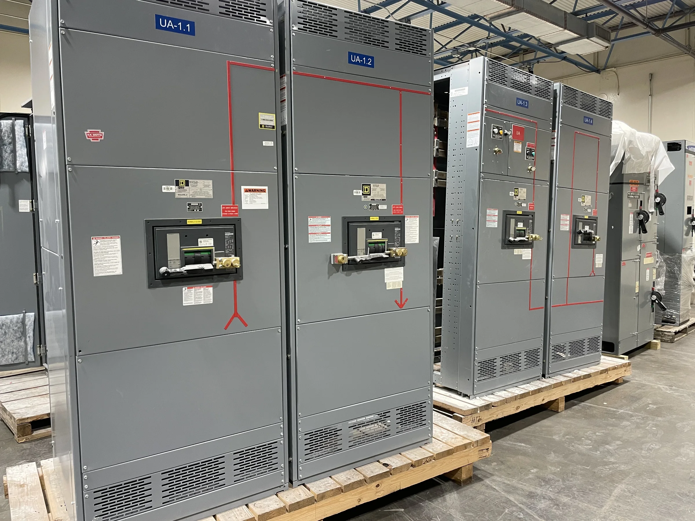
Coordinate Switchgear With the Plant’s Electrical One-Line
A power plant’s medium-voltage lineup must fit the intended connection between generators, transformers, auxiliary loads, and the utility or site distribution system. Start procurement with the current one-line diagram and identify each source, bus section, tie, feeder, and normal or alternate operating path. Those details affect lineup arrangement, protective-device selection, metering, controls, and whether operators can isolate a section without unnecessarily interrupting other loads. Confirm system voltage, frequency, available fault current, grounding method, and required continuous and short-circuit ratings with the project engineer; do not infer them from a nearby installation. A U.S. manufacturer can build new equipment around approved project requirements, but the final configuration and ratings must be validated for the specific system.
Match Protection and Controls to Operating Scenarios
Protection decisions should reflect how the plant actually operates, not just the normal running condition. Review generator and transformer contributions, utility backfeed, bus-tie operation, motor starting, and any planned islanded or standby modes with the protection engineer. These scenarios can change fault-current levels and coordination requirements, so relay functions, settings, CT and VT data, trip circuits, and interlocks need to align with the approved study and control philosophy. Identify interfaces to plant DCS, SCADA, synchronizing, or load-shedding systems, including signal ownership and communications expectations. Mismatched control assumptions can delay commissioning or create confusing alarms. Define required drawings, I/O lists, relay documentation, and review milestones before release; settings and compatibility remain project-specific.


Specify Equipment for the Plant Environment
Power-plant locations impose different demands on switchgear. A clean, conditioned electrical room has different requirements from a turbine hall, boiler area, outdoor enclosure, or site exposed to dust, moisture, corrosive atmosphere, or temperature extremes. Document the actual installation environment, indoor or outdoor placement, elevation where relevant, ventilation, access, and expected exposure to vibration or contaminants. These conditions influence enclosure construction, space planning, heaters or other environmental provisions, and maintenance intervals. Do not select an enclosure or environmental rating by appearance alone; confirm the governing project criteria and applicable standards with the design team. For low-voltage switchboard assemblies, UL 891 may be relevant when the assembly is appropriately evaluated; it is not a blanket certification for medium-voltage switchgear.
Resolve Room Layout, Cable Entry, and Maintenance Access
A lineup that meets electrical requirements can still create costly site changes if its physical interfaces are overlooked. Provide room dimensions, equipment arrangement, door and aisle clearances, ceiling height, cable-trench or conduit locations, and the intended routing for incoming and outgoing conductors. Confirm cable entry direction, termination space, bending room, and whether the installation plan calls for top or bottom access. Include the delivery route from the receiving point to the final room: turns, ramps, door openings, floor loading, lifting points, and any restrictions on moving equipment in sections. Maintenance access also matters; operators need room to inspect and service equipment safely under approved procedures. Review outline and interface drawings before construction so civil, electrical, and equipment packages agree.
Build a Complete Procurement and Review Package
A clear request for quotation helps engineers compare compliant proposals instead of reconciling different assumptions after award. Include the one-line, equipment schedule, project specifications, system study data, protection requirements, control diagrams, environmental conditions, and required accessories or spares. Identify applicable codes and standards, documentation formats, inspection or witness points, and the parties responsible for approving drawings and settings. Ask the manufacturer to identify exceptions and open technical questions explicitly; an unstated assumption about fault duty, metering, communications, or compartment arrangement can become a change later. Review submittals against the approved design and record decisions in a controlled comment log. Scope, evaluation requirements, and final equipment configuration should be agreed project by project, rather than treated as automatically included.
Plan Schedule, Delivery, and Site Readiness Together
Discuss timing early, because drawing approval, component availability, custom construction, inspections, and shipping all affect the project sequence. A U.S. manufacturer may offer short lead times, but no duration should be assumed until the exact scope, approvals, and availability are confirmed. Set realistic dates for technical submittals, review turnaround, release to production, required inspections, and delivery coordination. Nationwide shipping does not remove the need to plan unloading: confirm the receiving location, access restrictions, lifting equipment, storage conditions, and who accepts and protects the shipment. Before dispatch, align delivery with room completion, cable preparation, grounding provisions, and the site’s installation and commissioning plan. A readiness checklist helps prevent equipment from arriving before the facility can receive it or support safe installation.