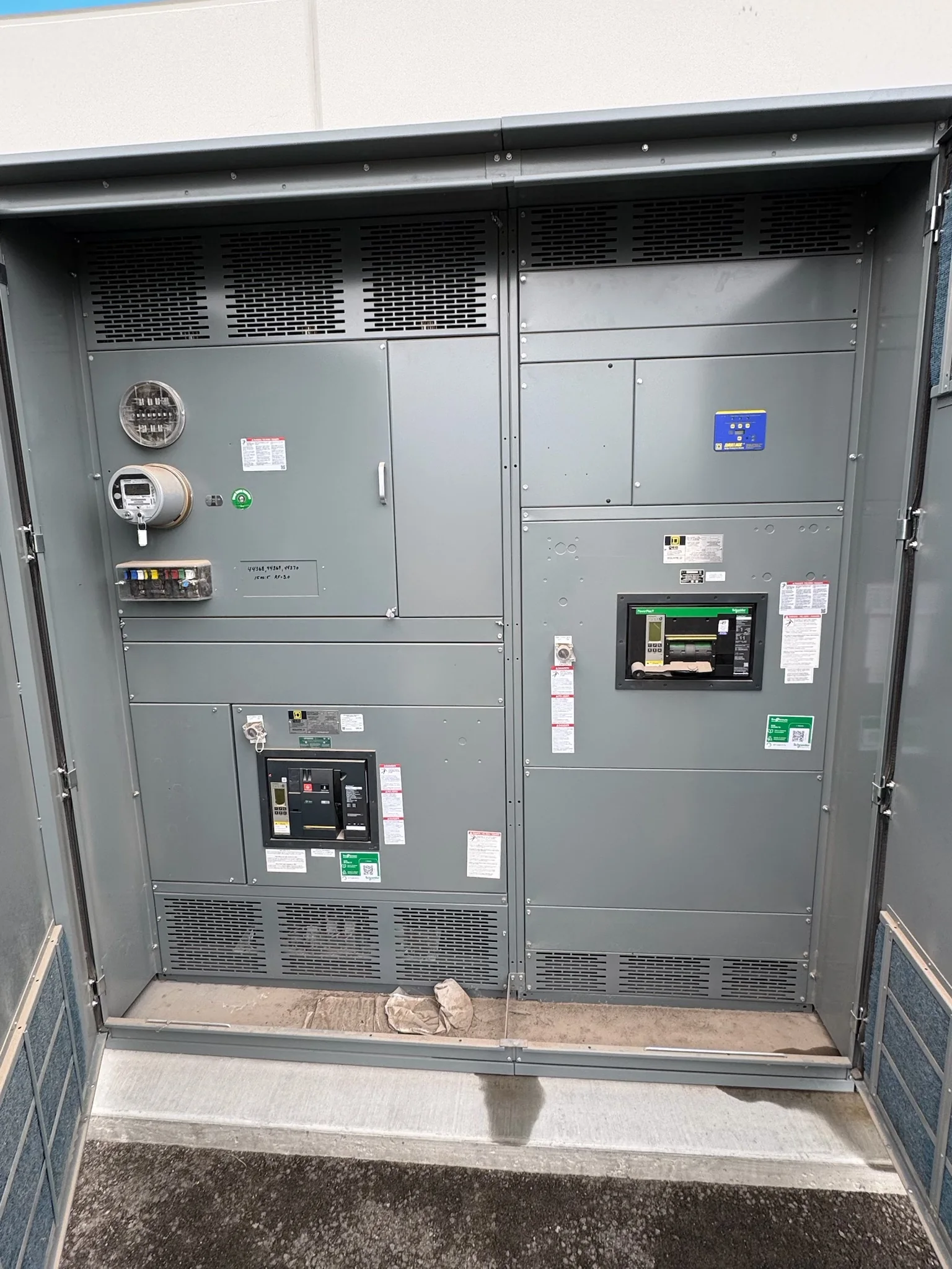
Define the Utility Duty Before Selecting the Lineup
Utility medium-voltage switchgear must be selected around the actual duty of the circuit, not just a nominal voltage. Start with the system voltage and frequency, continuous current, available fault current, required interrupting capability, and the way the equipment will be operated. Protection philosophy matters too: feeder coordination, transformer protection, bus protection, and tie or transfer schemes can change the lineup arrangement and relay requirements. Document normal and contingency operating conditions, including whether parallel sources are possible. These details affect equipment ratings, compartment layout, control power, and interfaces with upstream and downstream devices. A U.S. manufacturer can build around project specifications, but ratings and configuration must be reviewed against the utility’s system data and applicable project requirements before procurement.
Coordinate Protection, Controls, and Utility Interfaces
A lineup that fits electrically can still delay commissioning if its controls do not match the utility’s operating and protection practices. Identify relay functions, trip and close circuits, control voltage, communications protocols, metering needs, and required indications early. Clarify whether the owner expects local control, remote supervisory control, or both, and define how alarms and status points will reach the control system. Protection settings are typically developed or approved by the responsible utility or engineer; procurement documents should distinguish supplied relay hardware from setting calculations and field commissioning responsibilities. Include current transformer and voltage transformer requirements, polarity and grounding conventions, terminal plans, and interface points. Resolving these items before release reduces wiring changes, testing gaps, and disagreement over who provides each component.


Specify Construction for the Installation Environment
Utility sites can expose switchgear to temperature extremes, moisture, dust, salt, vibration, or limited ventilation, depending on location and enclosure. State indoor or outdoor service, environmental conditions, enclosure requirements, cable entry direction, access clearances, and any site-specific corrosion or seismic criteria in the inquiry. These conditions affect construction choices and may influence heaters, ventilation, insulation, and maintenance access; they should not be assumed from a generic equipment description. Confirm whether the lineup will sit in a substation building, control house, prefabricated enclosure, or open yard, and coordinate dimensions and cable routing with the civil and electrical drawings. The manufacturer can evaluate a custom build against the project brief, while final suitability depends on documented conditions and approved engineering.
Plan a Replacement Around Outage and Site Constraints
Replacing existing utility gear is often governed by outage windows, foundation geometry, and the condition of connected cables more than by the switchgear footprint alone. Gather existing one-lines, elevations, bus and cable termination details, control schematics, and nameplate information where available. Verify access routes, lifting limits, door openings, floor loading, anchorage, and space for safe maintenance before finalizing the arrangement. Existing conduits and cable lengths may not align with a new lineup, so identify which connections can be changed and which must remain. A replacement or retrofit scope should clearly assign demolition, temporary service, cable work, testing, and commissioning. Planning these interfaces early helps the project team compare alternatives and schedule de-energized work without treating an assumed fit as confirmed.
Build a Complete Submittal and Purchasing Package
A clear request for quotation gives procurement and engineering a common basis for comparing equipment. Provide the project one-line diagram, equipment schedule, technical specification, site conditions, required options, preferred delivery destination, and milestone dates. Ask bidders to identify exceptions, assumptions, and items excluded from their scope rather than relying on a price alone. Submittals may need general arrangement drawings, elementary and connection diagrams, bills of material, relay data, and installation or maintenance documents; confirm the required review sequence and approval status in the purchase documents. Identify applicable standards and any required inspection or testing explicitly, then confirm applicability for the particular assembly and project. UL 891 applies to appropriately evaluated low-voltage switchboard assemblies, not automatically to medium-voltage switchgear.
Coordinate Delivery, Receiving, and Commissioning Readiness
Nationwide shipment does not remove the need to plan how utility switchgear will reach its final location. Confirm the delivery address, receiving hours, site access, unloading equipment, storage conditions, and whether a carrier can reach the installation area. Long or heavy sections may require a defined offload sequence and protected staging space; verify handling instructions and shipment configuration with the manufacturer before dispatch. Align the requested delivery timing with drawing approvals, foundation completion, cable procurement, outage planning, and the availability of installation crews. Before energization, the responsible project team should verify installation, grounding, cable terminations, protection settings, and required acceptance checks under approved procedures. Specific equipment configuration, standards, testing scope, and shipment timing remain subject to project review and confirmed availability.