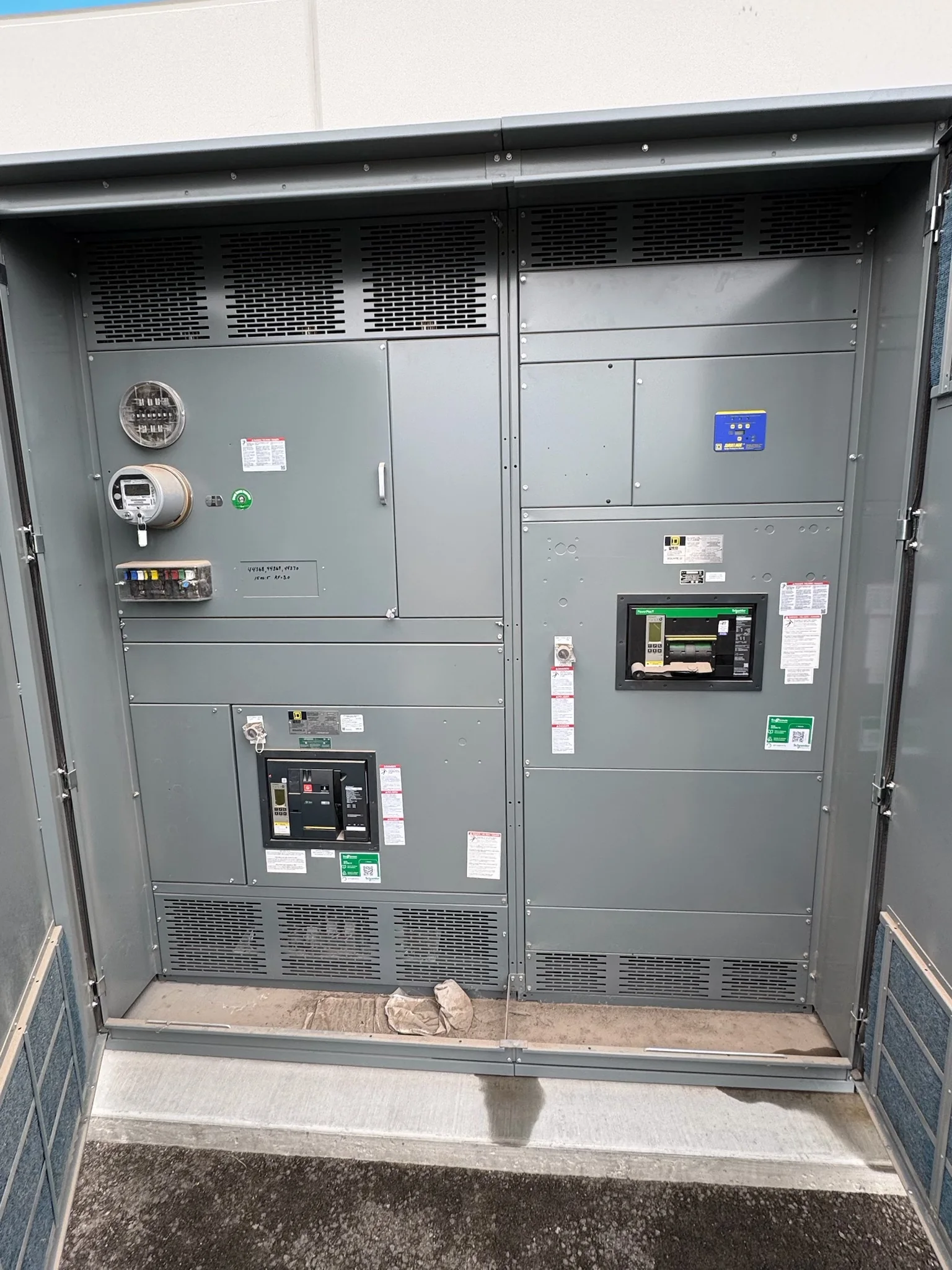
Start With the Switchboard’s Electrical Duty
A molded case circuit breaker (MCCB) is not selected by frame size alone. Begin with the switchboard’s system voltage, phase and wire configuration, available fault current, and the load served by each feeder or main. The breaker’s interrupting rating must be suitable for the fault current at its point of installation, and the assembly’s short-circuit rating and any tested series combination must be verified as a complete, compatible arrangement. These values are project-specific; a rating printed on an individual breaker does not establish the rating of the assembled switchboard. Provide the manufacturer with the one-line diagram, utility or upstream fault-current information, and operating conditions so proposed equipment can be reviewed against the actual distribution design.
Coordinate Trip Functions and Selective Coordination
Protection choices affect both equipment protection and how much of a facility loses power during a fault. Identify whether each MCCB needs a thermal-magnetic or electronic trip unit, adjustable settings, ground-fault protection, or coordination with upstream and downstream devices. Do not assume that similar frame sizes or trip ratings will produce selective coordination: actual time-current curves, tolerances, fault levels, and device combinations matter. Where life-safety, emergency, or process loads are involved, the engineer should document the coordination objective and applicable project requirements for review. Include the intended settings and any required field verification in the submittal process. Resolving these questions before release helps avoid late changes to breaker selection, protection studies, wiring, or the switchboard’s internal arrangement.


Confirm Breaker-to-Switchboard Compatibility
An MCCB must fit the switchboard’s design, not merely match an ampere value on a schedule. Confirm the specified manufacturer and breaker family, mounting arrangement, pole count, terminal orientation, bus connection, lug configuration, and any required accessories, such as shunt trips, auxiliary contacts, or undervoltage releases. A replacement breaker or retrofit may require a different review than a new assembly; physical fit alone does not establish electrical or listing compatibility. Provide existing switchboard nameplates, drawings, photographs, and breaker catalog information when planning a replacement or modification. The manufacturer can assess the requested configuration against available design information, but final suitability, approvals, and any required evaluation depend on the equipment and project. This reduces surprises during submittal review and installation planning.
Build a Complete Procurement and Submittal Package
A clear request for quotation should identify the switchboard lineup, service and feeder requirements, breaker quantities, ratings, trip functions, accessories, and required standards or project specifications. Attach the current one-line diagram, panel or load schedules, site environmental conditions, and any approved protection study or coordination requirements. Note whether equipment is new construction, an addition, or a replacement, and identify interfaces with existing gear. For low-voltage switchboard assemblies, UL 891 may be relevant when the specified assembly is appropriately evaluated; it is not a blanket designation for every breaker or for medium- and high-voltage equipment. Ask reviewers to flag open items and deviations in writing. A complete package supports a more accurate proposal and gives engineering, procurement, and the manufacturer a common basis for resolving exceptions.
Plan Schedule Around Design Release and Site Readiness
Custom switchboard configurations and breaker selections may require engineering review before production details are finalized, so schedule discussions should begin with the project’s required dates and approval milestones. Identify when drawings must be reviewed, when settings or accessories will be confirmed, and whether phased shipment or staged installation is requested. Short lead times may be available, but timing depends on the approved configuration, component availability, and project-specific requirements; do not treat an estimate as a guarantee until scope and schedule are confirmed. At the site, verify access routes, door and ceiling clearances, floor loading, housekeeping-pad dimensions, and the sequence for moving equipment into electrical rooms. Resolving these constraints early can prevent a delivered lineup from being delayed by an inaccessible route or unfinished installation area.
Coordinate Delivery, Installation, and Closeout Records
Nationwide shipping still requires site-level coordination. Before shipment, confirm the receiving contact, delivery window, unloading equipment and responsibility, staging area, weather protection, and any carrier or facility access rules. Check whether the switchboard will arrive as one lineup or in sections, and plan handling around the manufacturer’s shipping documents and approved installation instructions. At installation, qualified personnel should follow the equipment documentation and applicable electrical requirements; de-energize equipment before work and verify the safe work condition. Keep approved drawings, breaker and trip-unit data, settings records, test documentation, and any permitted deviations with the facility’s closeout files. These records help future maintenance teams identify the installed configuration and assess changes without relying on appearance or incomplete labels.