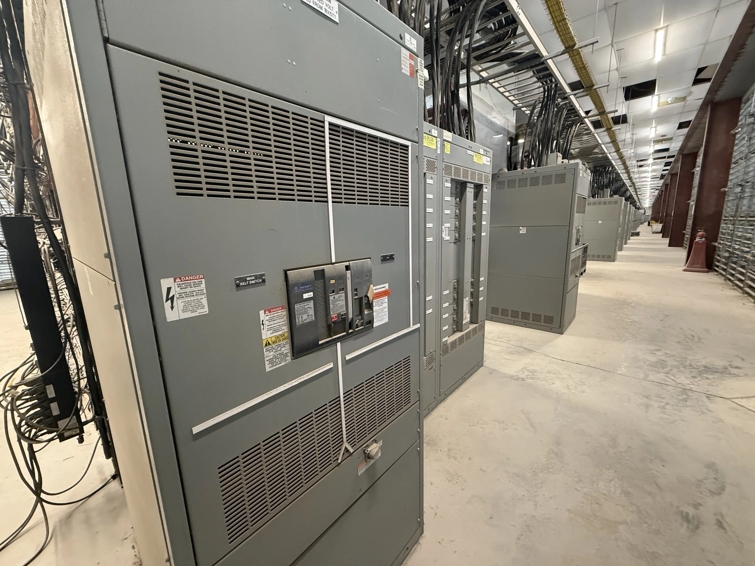
Match the MCC to the Plant’s Process
A motor control center (MCC) should reflect how production equipment operates, not just the number of motors on a one-line diagram. Start with the motor list, nameplate data, starting method, duty cycle, control voltage, and required protection for each load. Identify which motors are critical to a line, which can restart automatically, and which must remain off after a power interruption. These distinctions affect unit arrangement, control interfaces, and operating procedures. Process engineers and electrical designers should also flag future loads and planned production changes; reserving space may be useful, but spare sections and capacity must be engineered for the actual lineup. Clear operating priorities help the manufacturer develop a build that supports maintainability without over-specifying equipment.
Resolve Electrical and Control Interfaces Early
An MCC’s fit depends on the distribution system feeding it and the equipment communicating with it. The project team should confirm available voltage, phase, frequency, fault-current information, grounding method, feeder arrangement, and upstream protective-device coordination. For each motor unit, define starter or drive requirements, overload protection, control signals, network protocol, and any interface to a PLC or plant control system. A variable-frequency drive can affect heat, harmonics, bypass needs, and maintenance access, so it should be identified before the lineup is finalized. Where existing equipment remains in service, document its electrical and control characteristics rather than assuming a replacement will connect directly. Final ratings, protective settings, compatibility, and applicable standards are project-specific and require engineering review.


Plan for Dust, Heat, Washdown, and Maintenance
Manufacturing environments can expose electrical equipment to airborne dust, oil mist, moisture, corrosive materials, vibration, or elevated room temperatures. Describe the actual installation area—including cleaning practices, nearby process equipment, ventilation, and expected ambient conditions—so enclosure and cooling decisions address the site rather than an assumed factory floor. A washdown zone or conductive dust exposure may call for a different placement or enclosure approach than a clean electrical room. Heat from drives and closely grouped loads can affect component operating conditions; available ventilation and clearance must be considered together. Also identify the space required to open doors, withdraw or service units where applicable, and safely access cable terminations. Environmental suitability and maintenance clearances should be verified against project conditions and equipment documentation.
Verify Lineup Dimensions and Cable Access
A lineup that meets electrical requirements can still create installation problems if the room, conduit, or cable routes are overlooked. Provide current room plans, door and aisle dimensions, equipment clearances, floor conditions, ceiling obstructions, and the intended cable-entry direction. Check whether existing conduits align with the proposed section layout and whether incoming and outgoing conductors can be routed and terminated without obstructing adjacent equipment. Confirm the delivery path too: door openings, corridors, turns, elevators, loading areas, and any limits on section size can determine how equipment is transported and assembled onsite. These checks matter especially in operating plants where expansion space is tight and shutdown windows are limited. Final dimensions, anchoring, access, and installation requirements must be coordinated with approved drawings.
Prepare Submittals Around Procurement Decisions
A complete request for quote helps the manufacturer identify the intended scope and expose missing decisions before fabrication documents are reviewed. Include the one-line diagram, load or motor schedule, control schematics, available fault-current data, equipment location, preferred lineup arrangement, and known interface requirements. Note which items are required, which are preferred, and which remain open for engineering coordination. Procurement teams should also state the requested delivery destination, receiving constraints, unloading responsibility, and project milestones; timing depends on the finalized scope, approvals, component availability, and shipping arrangements. Ask for project-specific submittals that support review, such as general arrangement drawings, unit schedules, wiring information, and equipment data. Confirm document scope and timing during quotation rather than treating them as automatic or guaranteed.
Coordinate Delivery, Installation, and Startup Readiness
Nationwide shipment does not remove the need to plan how an MCC reaches its final location and becomes part of the plant system. Before release, align the approved configuration with site access, receiving hours, storage conditions, unloading equipment, and the sequence for moving sections into the electrical room. Protect equipment from moisture, debris, and physical damage during storage, and follow the manufacturer’s handling and installation instructions. Coordinate installation with qualified electrical personnel, required permits, plant safety procedures, and a defined outage plan. Equipment must be de-energized and verified safe before installation, inspection, or maintenance work; energized tasks require appropriate controls and qualified personnel. Before production relies on the lineup, complete project-specific inspections, connection checks, protection coordination, control integration, and startup approvals.