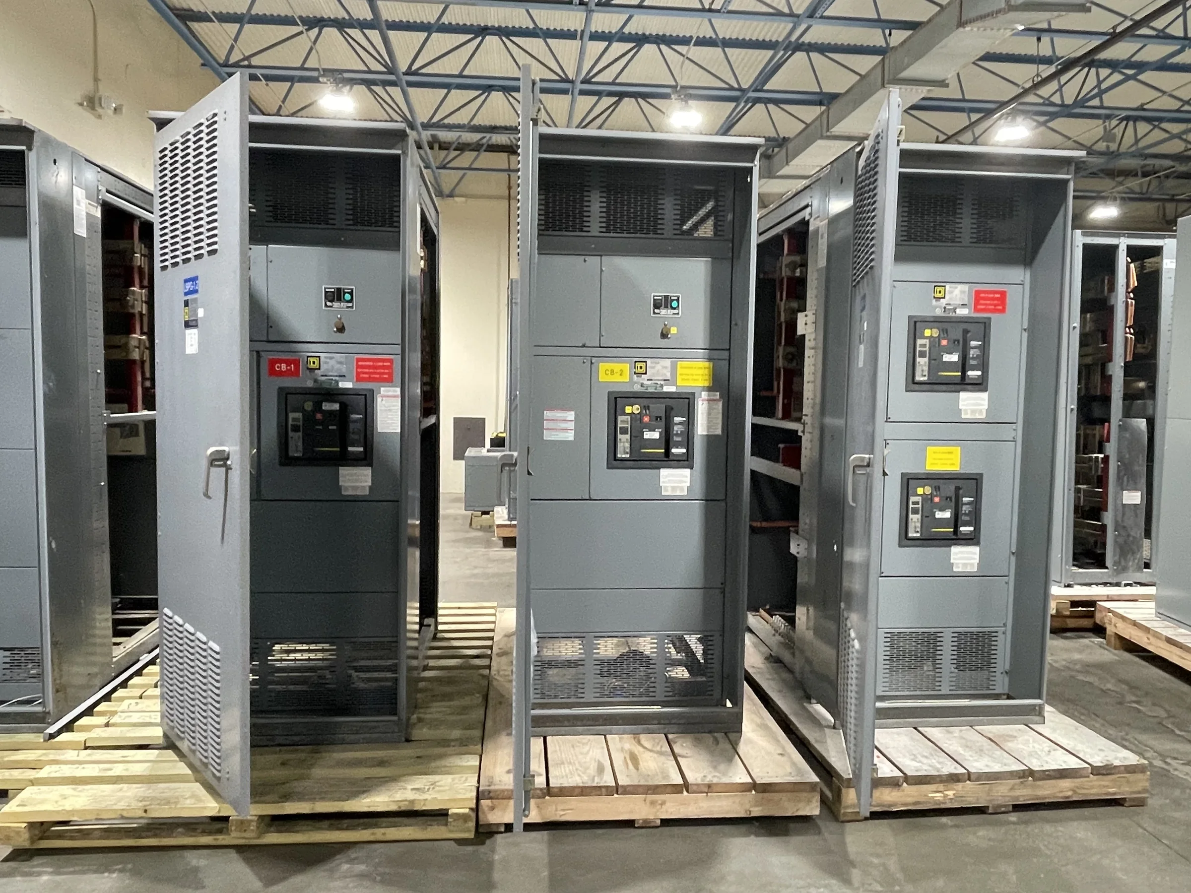
Match the MCC to the Facility’s Process and Power System
Oil and gas facilities bring together pumps, compressors, fans, conveyors, and other motor-driven loads, but the right motor control center (MCC) depends on how each load operates and how the site distributes power. Start with the one-line diagram, motor list, available fault-current information, and control philosophy. These inputs help the engineering team assess bus and short-circuit requirements, feeder arrangements, starter or drive types, and coordination with upstream protective devices. A compressor package with frequent starts may place different demands on its feeder and controls than a ventilation fan or utility pump. Confirm system voltage, grounding, operating sequence, and expansion plans before equipment is specified. Final ratings, component selection, and compatibility must be established for the actual project.
Account for Hazardous Locations and Outdoor Exposure
A facility’s classified areas, weather exposure, and process conditions can affect where MCC equipment may be installed and how associated circuits must be designed. Classification drawings and area boundaries should be reviewed alongside the equipment layout; an MCC’s location does not, by itself, determine whether connected devices or field wiring meet area requirements. Outdoor installations may also require attention to temperature range, moisture, dust, corrosive atmospheres, sun exposure, and enclosure placement. These conditions influence enclosure selection, cooling considerations, cable entry, and maintenance access. Provide the project’s environmental criteria and applicable design documents early, and have qualified project personnel verify code and hazardous-area requirements. Do not assume a standard indoor assembly or a particular enclosure rating suits every oil and gas site.


Choose Motor Starting and Control Around Operating Duty
The operating duty of each motor helps determine whether a starter, reduced-voltage starting method, or variable frequency drive is appropriate. Consider load inertia, starts per hour, acceleration time, process turndown, required speed control, and the effect of starting on the electrical system. Drives can support process control, but they also introduce heat, harmonics, and equipment coordination questions that should be addressed in the design. Define local and remote operating modes, permissives, interlocks, alarms, and shutdown interfaces with the controls team. Identify whether signals connect to a distributed control system, PLC, or package controller, and document the required interface. These choices affect MCC space, wiring, cooling, and commissioning; final selection depends on the motor, process, power system, and project requirements.
Coordinate Layout, Access, and Site Installation
A technically suitable MCC can still create costly field problems if its lineup, access, or cable routing conflicts with the building or process area. Confirm the equipment footprint, room clearances, door swing, aisle access, overhead restrictions, cable-tray routes, and entry direction against current civil, structural, and electrical drawings. Check the delivery path as well: door and corridor dimensions, turning space, floor loading, lift points, and available unloading equipment may constrain how sections reach their final location. In remote or congested facilities, plan staging and installation sequence with the site team before release for manufacture. Provide verified dimensions and site constraints for review, and resolve changes through controlled drawing updates. Installation and service work must follow approved procedures and be performed with equipment safely de-energized.
Build a Procurement Package That Supports Review
A complete inquiry makes technical review more useful and reduces the risk of assumptions carrying into an order. Send the latest one-line and three-line diagrams, motor schedule, load data, control narratives, communications requirements, site conditions, and applicable project specifications. Identify required submittal formats, drawing review milestones, inspection or witness-test expectations, spare parts, labeling conventions, and document language. If the project calls for UL 891, clarify whether the specified equipment is a low-voltage switchboard assembly within that standard’s scope; UL 891 is not a blanket certification for MCCs or medium- and high-voltage equipment. Any listing, evaluation, or standard requirement must be confirmed for the exact assembly. Resolve deviations, exclusions, and interface responsibilities in writing before purchase so bidders and project reviewers are working from the same basis.
Discuss Schedule, Manufacturing, and Delivery Early
Project timing depends on the approved design, component availability, review cycles, manufacturing scope, and site readiness—not simply on when a purchase order is placed. Share required in-service dates, decision deadlines, phased construction needs, and dependencies such as motor data or control-system interfaces when requesting a quote. A U.S. manufacturer can discuss custom builds, American components, short lead times, and nationwide shipping, but timing and availability must be confirmed for the specific configuration. Establish who will approve drawings, when comments are due, and how revisions affect release. Before shipment, coordinate packaging, section sizes, routing, unloading, receiving hours, and storage conditions with the destination site. Clear delivery planning matters especially where access is restricted or construction is staged, because arriving equipment cannot be installed until the room and handling plan are ready.