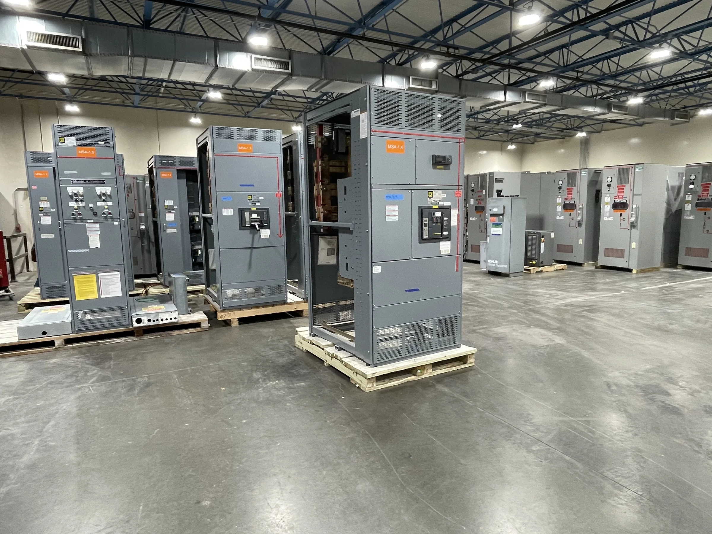
Start With the Loads and Operating Sequence
A port motor control center may serve conveyor drives, cranes, pumps, ventilation, lighting, or utility systems, but the equipment schedule alone does not show how those loads interact. Document each motor’s nameplate data, starting method, operating duty, expected starts per hour, and any required coordination with variable-frequency drives or soft starters. Then map which loads must remain available during maintenance or a fault. This matters where a stopped conveyor can interrupt cargo movement or a disabled dewatering pump can affect a work area. Identify local and remote control points, interlocks, alarms, and emergency-stop interfaces early. The manufacturer can use that information to develop a project-specific arrangement; ratings, protective-device selections, and compatibility must be confirmed against the final design.
Account for Salt, Moisture, and Outdoor Exposure
Marine terminals can expose electrical equipment to salt-laden air, wind-driven rain, condensation, and temperature swings. These conditions influence enclosure location and construction, ventilation, corrosion protection, and maintenance access; they do not automatically point to one enclosure type or rating. Decide whether the MCC will be indoors, in a conditioned electrical room, or outdoors beneath a shelter, and document nearby washdown, dust, and corrosive processes. Where moisture can form inside an enclosure, discuss the room’s environmental controls and any project-specific mitigation with the design team. A more protective enclosure may also affect cooling and dimensions. Confirm the required environmental ratings and materials for the actual installation rather than assuming a general marine designation covers every exposure.


Coordinate Power, Protection, and Controls
Available fault current, system voltage, grounding method, and upstream protective devices shape MCC selection and feeder coordination. Provide the one-line diagram, short-circuit and coordination studies when available, and source-transformer information so the equipment can be evaluated for the intended system. Motor circuit requirements also depend on the starter or drive, branch-circuit protection, and the control scheme. For variable-speed applications, clarify drive locations, cable routes, harmonic considerations, bypass needs, and interfaces to the terminal’s control network. These details matter because a lineup that fits the motor list may still conflict with the electrical study or control architecture. Final ratings, device combinations, and standards applicability are project-specific and should be reviewed by the responsible engineer and manufacturer.
Fit the Lineup to the Electrical Room
Existing port facilities often impose tight room dimensions, fixed cable-entry points, overhead obstructions, and limited space for future service. Before approving a layout, verify clear working space, door swings, pull-box locations, conduit or tray approaches, ventilation, and the path for removing equipment sections. Confirm whether incoming and outgoing cables enter from above or below; changing that assumption late can affect structure and installation planning. Record room access dimensions and the route from the delivery point, including turns, ramps, floor capacity, and any lift restrictions. These checks matter because a lineup can meet its electrical requirements yet be difficult to position or maintain in the available space. Final arrangement and installation clearances require project review.
Prepare Submittals for Review and Release
A complete request for quotation helps the procurement team compare suitable equipment and reduces avoidable clarification cycles. Include the load schedule, one-line diagram, control schematics or sequence narrative, available fault-current data, specified standards, environmental conditions, and preferred enclosure location. Identify required spare compartments, future motor provisions, metering, communications, and any division of supply between the MCC and field devices. Ask the manufacturer to identify assumptions and exceptions in the proposal, then route drawings through electrical, controls, operations, and maintenance reviewers. Resolve comments before release for production: a late change to motor data, cable entry, or control interface can affect layout and procurement. Confirm project-specific approvals, documentation, and any requested evaluation or labeling; UL 891 applies only where appropriate to evaluated low-voltage switchboard assemblies.
Plan Delivery Around Terminal Operations
A port delivery is not complete when the equipment reaches the gate. Coordinate the requested ship window with terminal access rules, receiving hours, security clearance, unloading equipment, laydown space, and the route to the electrical room. Vessel schedules, cargo traffic, and restricted work zones can limit when trucks or lifting equipment may move, so confirm site requirements before setting a delivery plan. Protect the lineup from weather and handling damage during staging, and assign responsibility for inspection, storage, and movement after receipt. Share the destination, unloading constraints, and installation sequence with the U.S. manufacturer during quotation and order review. Custom builds, American components, short lead times, and nationwide shipping are available offerings; exact configuration, schedule, and delivery arrangements depend on project requirements and confirmation.