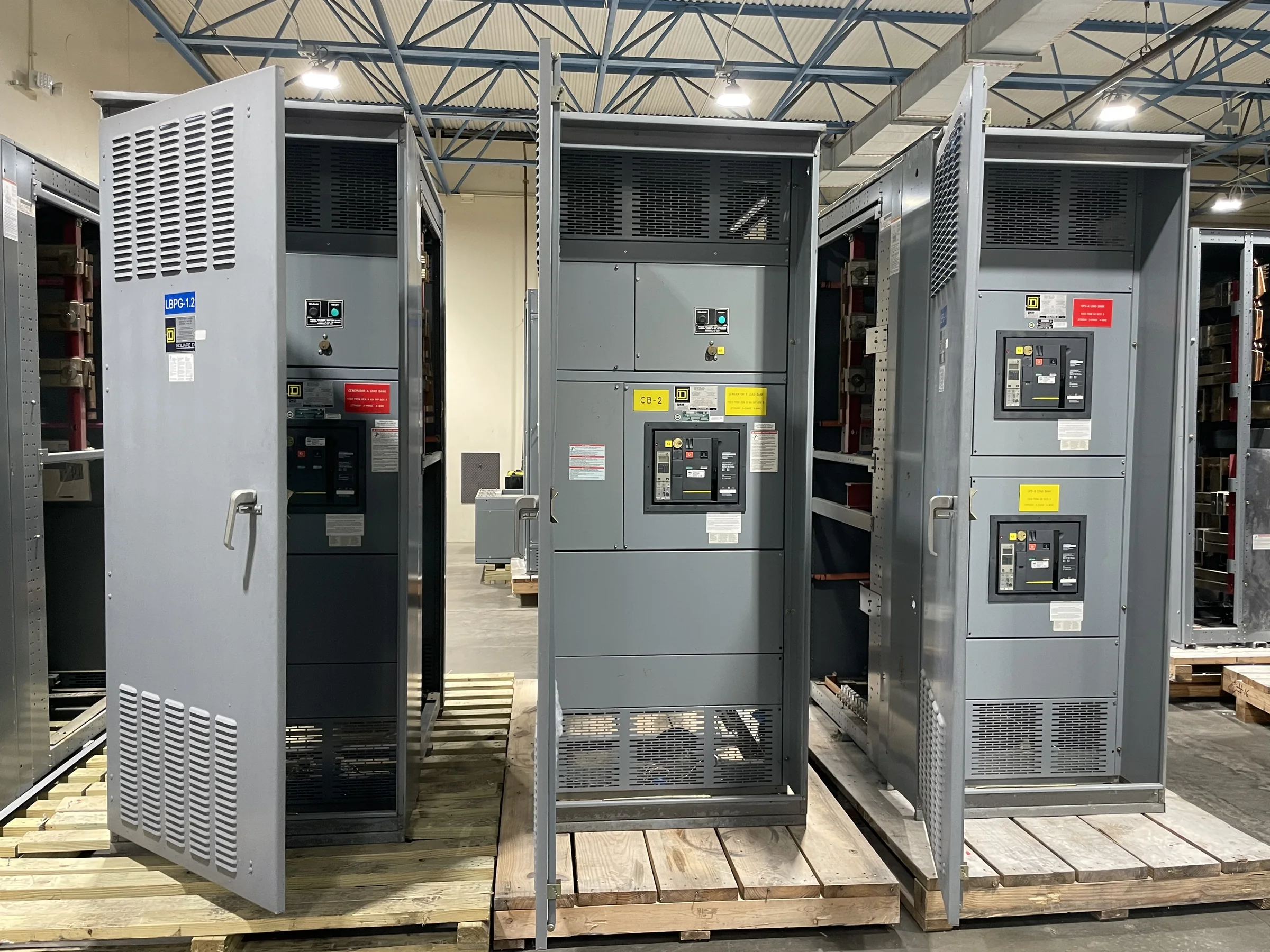
Match the MCC to the Treatment Process
Wastewater motor control centers may serve influent pumps, screens, grit removal, aeration blowers, return activated sludge pumps, dewatering equipment, and chemical-feed systems. These loads do not all behave alike: some run continuously, some cycle with process demand, and others must respond to a level, flow, pressure, or equipment-status signal. Start the specification with the process equipment list and control narrative, not simply a count of motor starters. Identify motor nameplate data, starting method, duty, required local controls, and interfaces to plant automation. This helps the design team distinguish across-the-line starters, reduced-voltage starting, or variable-frequency drives where the application supports them. Final device selection, ratings, and coordination require project-specific engineering and confirmation against the connected equipment.
Account for Moisture, Corrosion, and Heat
A wastewater building can expose electrical equipment to persistent humidity, condensation, corrosive gases, washdown, and airborne contaminants. Conditions vary between a dry electrical room, a screening area, and a space near process tanks, so the MCC location and enclosure requirements should reflect the actual environment. Provide the manufacturer with room temperature range, ventilation or cooling details, elevation, expected exposure, and any cleaning practices that could affect the enclosure. Heat deserves particular attention when drives or other heat-producing devices are concentrated in a lineup: room cooling and equipment spacing can affect practical arrangement and operating conditions. Do not assume a standard enclosure or ventilation approach suits every room. Confirm environmental suitability, enclosure construction, and any applicable ratings for the specific assembly and installation.


Specify Controls, Signals, and Future Changes
The control interface can be as consequential as the motor rating. Document whether each load is operated locally, from a plant control system, or in both modes; identify required permissives, interlocks, alarms, and status indications. For networked devices, specify the intended communication architecture and who supplies, configures, and tests each connection. Clear responsibility prevents gaps between the MCC, process controls, instruments, and contractor-installed wiring. Also consider how maintenance staff will isolate equipment and identify a fault without disrupting unrelated process loads. If future capacity or spare sections are important, describe the intended expansion and available room rather than relying on an assumed empty bucket or lineup space. The manufacturer and project engineer can then review feasible arrangements and interface details before release.
Resolve Protection and Electrical Data Early
A complete request for quotation should include available system voltage, phase and frequency, service configuration, fault-current information, grounding method, and the project's protection and coordination requirements. These inputs affect equipment ratings, protective-device selection, and the connection to upstream and downstream distribution. Where the supply or site data remain preliminary, label assumptions clearly and identify who will confirm them before approval drawings or production. For drives and other electronic loads, review the specified motor behavior and system requirements with the responsible engineer; do not presume one protective or filtering arrangement fits every application. Low-voltage switchboard assemblies evaluated to UL 891 are distinct from motor control center assemblies, and that standard is not a blanket certification for all equipment. Applicable standards, evaluation, ratings, and labeling must be confirmed for the actual product and scope.
Plan Submittals Around Procurement Milestones
Timing is easier to manage when the purchase package defines decisions that can hold up engineering: approved motor schedules, control schematics, communications requirements, site conditions, and the responsible parties for review. Request drawings and documentation appropriate to the project, such as lineup dimensions, connection details, device data, control diagrams, and installation or operating information. Review submittals against the process sequence and electrical design, then return consolidated comments through the designated approval path. A U.S. manufacturer can discuss custom construction, American components, and current production timing for the requested configuration, but availability and delivery depend on project details and confirmation. Treat quoted schedules as project-specific, and allow for review, revisions, shipping coordination, and receiving constraints rather than assuming a standard lead time.
Coordinate Delivery and Installation Readiness
A wastewater facility may have narrow access routes, active treatment operations, restricted laydown space, or limited crane and rigging access. Before ordering, share doorway and route dimensions, unloading capabilities, destination conditions, and any limits on delivery hours or vehicle access. Confirm the proposed lineup arrangement and shipping configuration against the route from receiving point to electrical room; equipment that fits the room may still be difficult to move into it. Coordinate foundation or housekeeping-pad readiness, conduit entry locations, anchorage details, and utility shutdown windows with the installing contractor and facility team. Nationwide shipping can support projects across the United States, but shipment planning and timing are specific to the order and destination. Installation, inspection, testing, and energization should follow approved project documents and be performed by qualified personnel.