Define the MCC Around the Motor Loads
Start a motor control center (MCC) specification with the connected equipment, not a preferred lineup layout. Provide a motor schedule showing each load’s nameplate data, starting method, duty, operating sequence, and any required reversing or speed control. Identify which motors run together, which are standby units, and whether future sections or spare buckets are expected. Those details affect feeder sizing, coordination, heat within the lineup, and available space. Also flag loads with frequent starts, high inertia, or process-critical service; their operating demands can change the appropriate control arrangement. For a Cypress project, include the plant’s process and expansion assumptions in the same review. A complete load basis helps the manufacturer develop a buildable proposal and reduces late changes that can disrupt procurement, drawings, and installation planning.
Resolve Electrical Data Before Selecting Components
An MCC’s interrupting and withstand requirements depend on the available fault current and the upstream protective devices, so do not treat voltage and motor horsepower as a complete specification. Share the system voltage, phase and frequency, grounding arrangement, source information, and fault-current study or other project basis available to the design team. Identify the upstream breaker or fuse type, settings, and coordination requirements, along with any arc-flash or selective-coordination criteria established by the engineer. If the service or transformer is changing, older fault-current calculations may no longer describe the installation. Confirm whether the lineup must interface with existing switchgear, cable, or bus connections, and provide verified dimensions and connection details. Final ratings and component compatibility are project-specific and should be confirmed against the approved design.


Choose Controls and Protection for the Process
Select each starter and control method to suit the driven equipment and process, rather than assuming every motor needs the same arrangement. Across-the-line starters may fit some loads; reduced-voltage starting or variable-frequency drives may be considered where starting current, acceleration, speed control, or process requirements call for them. Drives can introduce heat, harmonics, and equipment-compatibility questions that belong in the design review. Specify overload protection, short-circuit protection, control voltage, enclosure conditions, and required interlocks in coordination with the electrical engineer and equipment suppliers. Document how local controls, remote commands, permissives, alarms, and emergency stops should interact. For pumps, fans, conveyors, or compressors, clarify operating sequences and service conditions. The right decisions support dependable operation and maintenance access without implying that one starter type or protective setting suits every application.
Coordinate Cypress Site Conditions and Delivery
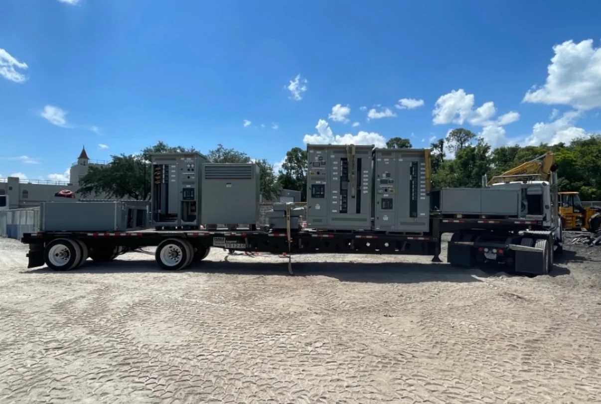
Delivery planning in Cypress should account for the actual receiving route and installation location, not just the project’s mailing address. Confirm truck access, gate restrictions, overhead clearances, turning space, unloading equipment, and whether the receiving area can accept the shipment in one delivery or requires phased coordination. Texas heat, humidity, dust, and exposure during construction can affect how electrical equipment should be stored and protected; agree on suitable handling and indoor staging with the project team. Verify the electrical-room entrance, corridors, door openings, and final setting path against the proposed lineup dimensions before approving the layout. Identify who will receive, inspect, and secure the equipment, and whether site readiness depends on other trades. Nationwide shipping and delivery timing should be discussed against the project schedule; availability and transit details require confirmation for the specific order.
Review Drawings, Interfaces, and Scope Before Release
Before manufacturing release, compare the equipment proposal with the approved one-line diagram, motor schedule, control schematics, and project specifications. Review lineup elevation and footprint, cable entry and termination space, incoming and outgoing connections, bus arrangement, nameplate information, and any required metering or communications interfaces. Confirm which items are furnished by the MCC manufacturer and which belong to the electrical contractor, engineer, or control-system supplier. That scope check matters because overlooked network gateways, auxiliary contacts, control transformers, or field wiring can create costly work at installation. Record deviations and open questions in a single review set, and identify who has authority to approve them. For low-voltage switchboard assemblies, UL 891 may apply when the assembly is appropriately evaluated; it is not a blanket certification for all MCC equipment. Applicable standards and labeling must be confirmed for the specified assembly.
Plan Purchasing, Schedule, and Future Service
A useful purchase package gives the manufacturer enough information to price the intended equipment and identify unresolved decisions: project voltage and fault basis, motor list, starter requirements, environmental conditions, drawings, requested delivery window, and applicable specifications. Ask which assumptions are included in the proposal and which options could change price or schedule, then track approved revisions so procurement and engineering work from the same version. Custom-built equipment and short lead times may be available, but neither a date nor a configuration should be treated as guaranteed before the project requirements and current availability are reviewed. Include commissioning and maintenance needs in the planning conversation: document spare-space expectations, access for routine service, replacement component identification, and who will provide startup support if required. Early alignment lets Cypress-area project teams coordinate equipment release with room readiness, contractor sequencing, and the broader construction schedule.