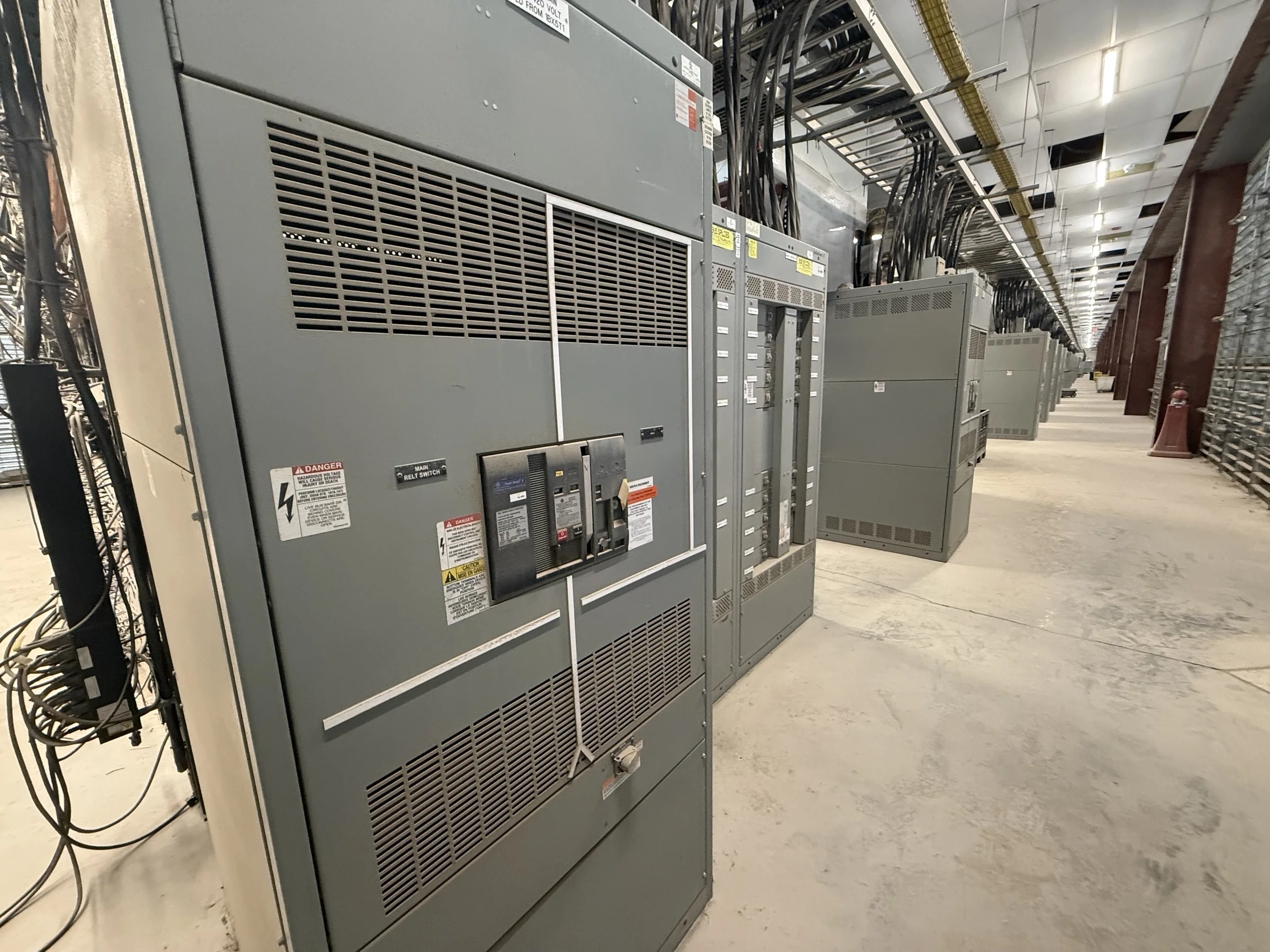
Define the Motor Control Center Around the Loads
For a Humble facility, start the specification with the motor-driven equipment and the way each load operates, rather than with a preferred enclosure or starter arrangement. Identify motor horsepower and voltage, full-load current, starting method, duty cycle, control voltage, and whether the equipment serves pumps, fans, conveyors, compressors, or process machinery. Note which loads must run together and which need interlocking, sequencing, or local control. These details shape the lineup, unit mix, bus requirements, and control provisions; omissions can create costly redesign or leave an operator without a needed function. Distinguish existing conditions from desired changes, especially when replacing equipment. A U.S. manufacturer can develop a new custom-built MCC around documented project requirements, subject to engineering review.
Resolve Electrical Ratings and Available Fault Current
A motor control center’s voltage, bus rating, and short-circuit requirements must fit the facility’s electrical system and the protection scheme feeding it. Provide the available fault current at the proposed connection point, upstream protective-device information, grounding arrangement, and any study assumptions that affect equipment selection. The engineer should confirm coordination and interrupting or withstand requirements for the complete installation; a number copied from an old drawing may no longer reflect utility changes or added transformers. Also identify ambient conditions and any specified enclosure or environmental requirements. This matters in Humble-area industrial and commercial sites where equipment may be installed in process, utility, or service spaces with different exposure and ventilation conditions. Final ratings and construction are project-specific, not assumed from location alone.


Choose Starters, Drives, and Control Interfaces Deliberately
Select each motor branch according to how the machine starts, stops, and responds to process demands. Across-the-line starters may suit some loads, while reduced-voltage methods or variable-frequency drives can be appropriate when starting impact, speed control, or process behavior calls for them. Drive selection also affects heat, harmonics, bypass needs, cable routing, and maintenance access, so document the application and operating sequence before fixing the lineup. Identify control-system interfaces, communications expectations, interlocks, alarms, and who supplies field devices or programming. A mismatch between the MCC and plant controls can delay commissioning even when the power equipment is correct. Confirm drive and starter details with the equipment and controls teams; availability, compatibility, and final configuration depend on the project.
Check Replacement Fit and Room Constraints Before Release
When an MCC replaces existing equipment, compare the proposed lineup against verified field dimensions and electrical conditions—not only the old one-line diagram. Record room width and height, lineup depth, door swing, cable entry and exit locations, overhead obstructions, floor condition, anchoring needs, and clear working space. Check whether feeders, control wiring, and grounding conductors can reach the intended termination points. Existing bus or unit arrangements should not be presumed compatible with new equipment; replacement and retrofit scope requires review of the specific installation. For Humble facilities, confirm the delivery route from the receiving point to the electrical room, including dock access, turns, doors, elevators if present, and any handling limits. Early fit checks help prevent field modifications, access conflicts, and schedule disruption.
Build the Submittal Package Around Review and Coordination
Before requesting a quote, assemble the documents that let the manufacturer and project team evaluate the same scope: equipment schedules, one-line diagrams, control schematics, load data, fault-current information, room plans, and applicable project specifications. Mark drawing revisions and identify open items rather than allowing an unverified assumption to become a selection requirement. Ask reviewers to check lineup arrangement, unit functions, incoming and outgoing connections, control interfaces, and required labels or accessories. For low-voltage switchboard assemblies, UL 891 may be relevant when the specified assembly is appropriately evaluated; it is not a blanket designation for every motor control center or for medium- and high-voltage equipment. Confirm applicable standards and evaluation requirements for the actual equipment and project. Clear submittals reduce review cycles and clarify responsibility.
Coordinate Manufacturing, Delivery, and Site Readiness
Discuss timing early, using the approved scope, drawing-review process, component selections, and required delivery sequence as inputs rather than relying on an assumed lead time. Custom builds and American components may be available options, but configuration and availability vary by project; request confirmation for the specified equipment. For delivery to Humble, Texas, coordinate the receiving contact, site access hours, unloading equipment, staging area, and route to the installation location. Confirm whether the lineup will arrive in sections and how each section will be handled, supported, and protected before installation. Before energization, qualified personnel must complete installation checks and required commissioning steps with the equipment de-energized wherever applicable. Nationwide shipping can support project logistics, but delivery dates and handling arrangements should be confirmed against the site plan.