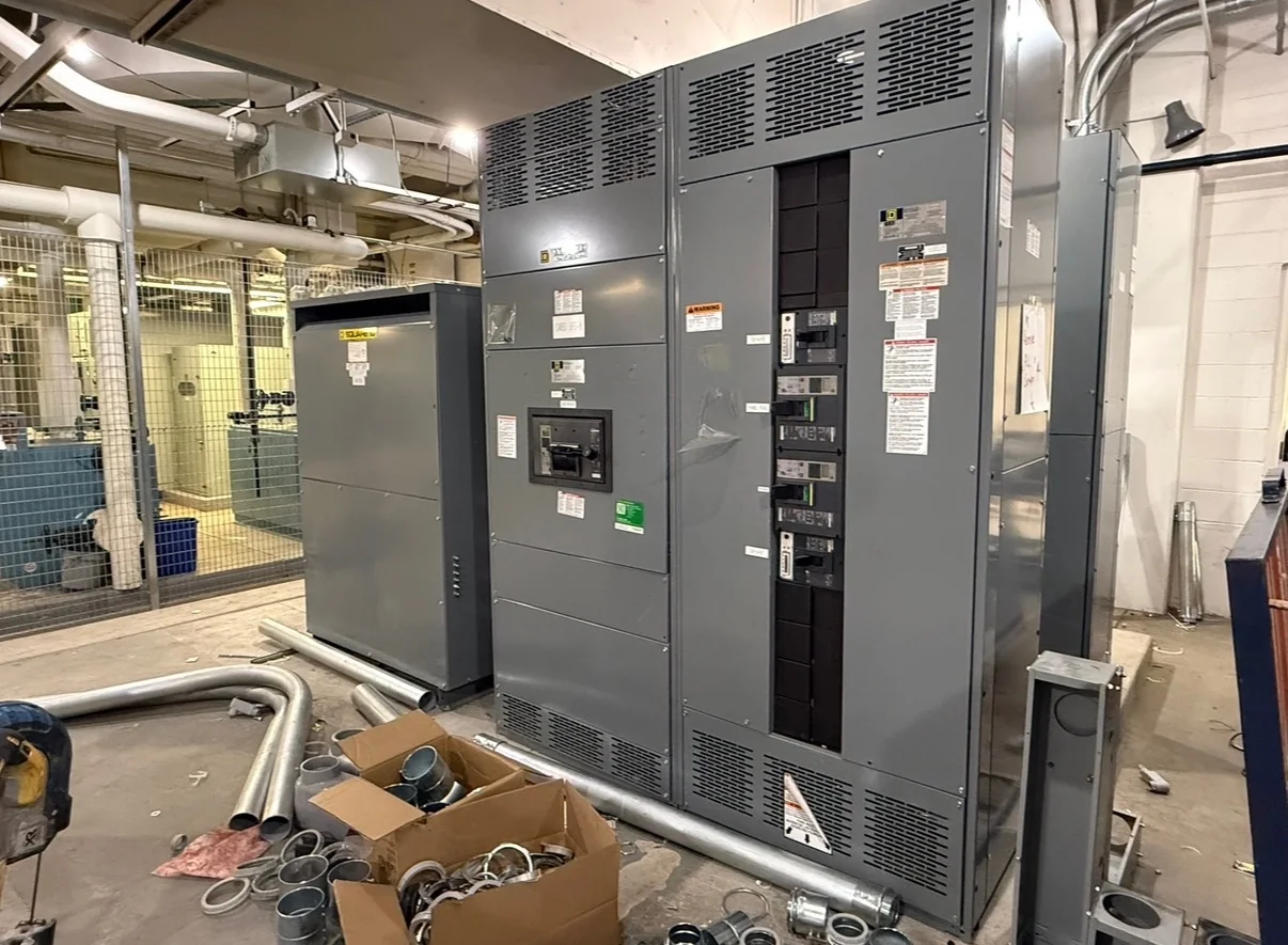
Define the MCC Around the Motor Loads
Start the specification with the driven equipment and operating sequence, not a preferred lineup arrangement. For each motor, document voltage, horsepower or full-load current, starting method, overload requirements, duty cycle, and whether the load needs reversing, speed control, or a soft start. Identify which motors must operate together and which are interlocked, because these details affect starter selection, bus loading, and control architecture. Also distinguish continuous process loads from intermittent or standby loads; treating every motor as identical can lead to an unsuitable arrangement or unnecessary complexity. For a Spring, Texas facility, include the operating environment and any process-critical loads in the equipment schedule. The manufacturer can then review the project requirements and develop a new motor control center proposal around the documented application.
Coordinate Electrical Ratings and Available Fault Current
An MCC must be specified for the electrical system it will actually serve. Provide the system voltage, phase and frequency, grounding arrangement, upstream protective-device information, and available short-circuit current at the proposed connection point. The engineer should establish the required assembly ratings and verify that the selected protective devices and combination motor controllers are suitable for the application; do not assume ratings based only on a similar existing lineup. Where a project is replacing equipment, confirm whether the available fault current or upstream protection has changed since the original installation. That can affect equipment selection and coordination. For a Spring project, current one-line diagrams and utility or facility fault-current data help avoid decisions based on outdated records. Final ratings and compatibility remain subject to engineering review and the project’s applicable requirements.


Choose Starters, Drives, and Control Interfaces
The control scheme should match both the motor and the way operators use the process. Across-the-line starters may suit some loads, while reduced-voltage starting or variable-frequency drives may be appropriate where the application calls for managed inrush, speed adjustment, or process control. Confirm the required bypass arrangement, control voltage, communication interface, local operator devices, and signals exchanged with a PLC or building system. For drive-fed motors, document motor cable length, shielding expectations, environmental conditions, and any project requirements for filtering or harmonic review. These items influence the design and should be resolved before the equipment is released for manufacture. A pump, fan, or conveyor installation in Spring may have different operating sequences and maintenance needs, so identify the process behavior rather than assuming a standard starter lineup will fit.
Plan the Room, Access, and Installation Sequence
Physical fit is an electrical and maintenance issue, not just a footprint check. Verify available wall length, ceiling height, working space, door swings, cable-trench or overhead-entry locations, and the route from the receiving point to the electrical room. Record whether the equipment must pass through gates, corridors, or door openings, and check floor loading and housekeeping-pad details with the project team. Confirm front-access or other construction requirements only after reviewing the specific equipment arrangement. In Spring, delivery coordination may also depend on site access rules, construction traffic, weather exposure during unloading, and whether lifting equipment can reach the receiving area. These constraints matter because a lineup that fits on a drawing may still be difficult to move, position, terminate, or safely maintain at the installed location.
Prepare Submittals and Purchasing Information Early
A complete request for quotation gives procurement and engineering a clearer basis for comparing new equipment proposals. Include the motor schedule, one-line diagram, control schematics or sequence narrative, requested enclosure and entry arrangements, project specifications, and any preferred component or interface requirements. Identify the installation location, expected indoor or outdoor exposure, ambient conditions, seismic or other project criteria when applicable, and the required documentation. Ask the project team to flag unresolved items rather than allowing assumptions to become hidden in a purchase order. Review the proposed submittals for starter types, device coordination, control connections, dimensions, and exceptions before approving production. UL 891 applies to appropriately evaluated low-voltage switchboard assemblies; it is not a blanket certification for motor control centers or for medium- and high-voltage equipment. Applicable standards and evaluation must be confirmed for the actual assembly.
Align Production Timing, Delivery, and Startup Readiness
Discuss schedule needs with the U.S. manufacturer while the project scope is being developed, and confirm current availability and timing for the specific configuration rather than relying on a general lead-time assumption. Long-lead components, design approvals, revisions, and incomplete interface information can all affect the production sequence. Agree on the submittal review path, approval responsibilities, shipping destination, receiving contact, and whether delivery must be coordinated with a contractor or facility shutdown. Nationwide shipping can support projects in Spring, but the site team still needs a plan for unloading, inspection, protected storage, and movement into the electrical room. Before energization, qualified personnel should verify installation, connections, protection settings, and control interfaces in accordance with approved documents and applicable procedures. Keep the final drawings and equipment records available to operations and maintenance staff.