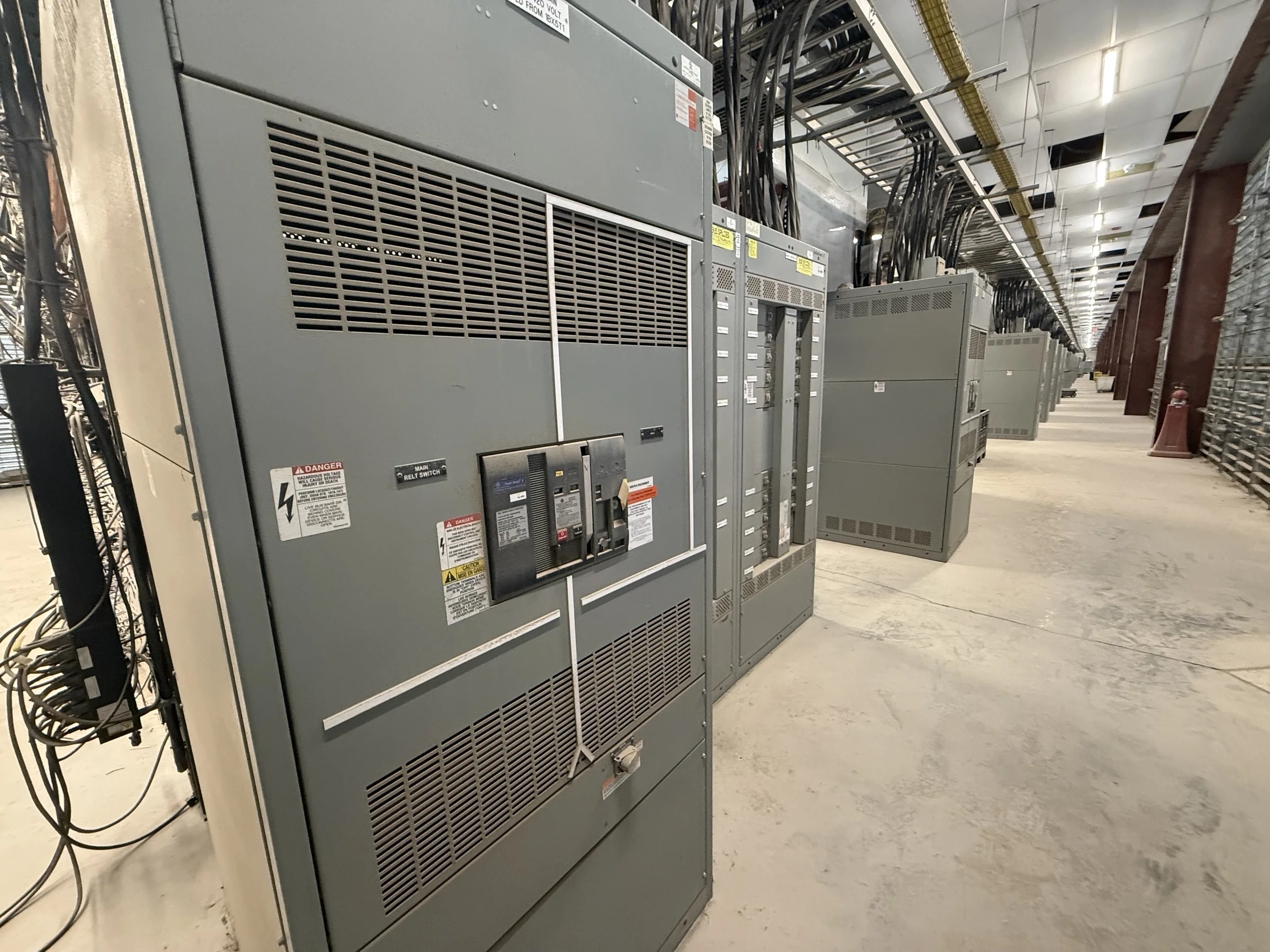
Define the Service-Entrance Arrangement Before Selecting Equipment
A commercial service entrance switchboard is the point where utility power enters the building’s distribution system, so the one-line diagram should establish its role before a manufacturer develops the build. Confirm whether the assembly is intended as service equipment, how many incoming sources or service sections are involved, and where metering, main overcurrent protection, and distribution sections belong. The serving utility’s requirements matter: metering provisions, service conductors, termination space, and acceptable arrangements can affect the design and may require utility review. Coordinate those decisions with the electrical engineer and authority having jurisdiction rather than relying on a general equipment description. A U.S. manufacturer can build around project specifications, but the applicable construction, ratings, and evaluation depend on the final design.
Coordinate Ratings, Fault Duty, and Protective Devices
Specify the system voltage, phase and wire configuration, frequency, and required continuous-current ratings for the service and outgoing feeders. Available fault current at the proposed equipment location is equally important: the engineer must establish the required short-circuit withstand or interrupting capability and coordinate protective-device selections with the system study. Do not assume a rating from an existing switchboard transfers to a replacement, especially if utility capacity, transformer impedance, conductor length, or protective settings have changed. Selective coordination, arc-flash analysis, and ground-fault protection requirements may influence breaker types, trip functions, and section arrangement. Provide the latest one-line diagram and fault-current data with the request for quotation; unresolved inputs can prompt design revisions and make price and schedule comparisons less meaningful.


Match the Enclosure and Layout to the Electrical Room
Room dimensions and access routes can rule out an otherwise suitable lineup. Measure the available wall length, ceiling height, working space, door swing, structural openings, and the route from the loading point to the final location. Identify whether conductors enter from above or below, where conduit stub-ups or cable trays land, and whether rear access is available. These details affect section widths, bending and termination space, enclosure selection, and installation sequence. Also account for heat, moisture, dust, corrosive exposure, and indoor or outdoor placement when specifying environmental protection; the appropriate enclosure depends on the actual conditions and project requirements. Confirm floor loading and anchorage with the responsible design team. Sharing a dimensioned room plan and access photos early helps uncover conflicts before equipment is released for manufacture.
Plan Metering, Feeders, and Future Capacity
The outgoing section schedule is more useful than a simple feeder count. For each load, provide breaker or fuse requirements, conductor information, equipment served, and any special protection or control needs. Confirm metering requirements with the utility and design team, including the intended measurement points and any provisions for monitoring. Spare spaces and future feeder capacity should be deliberate: an empty compartment is not automatically a usable future circuit if bus capacity, fault duty, heat rise, or physical layout was not designed for it. Likewise, replacing a main device can affect coordination and maintenance arrangements. Where continuity of service matters, discuss whether the project calls for separate service sections or other defined operating arrangements. The manufacturer can quote the specified configuration, but engineering review must confirm compatibility with the complete distribution system.
Set a Realistic Submittal and Manufacturing Schedule
A short manufacturing lead time is most useful when the project team supplies a complete, coordinated package. Include the one-line diagram, load and feeder schedules, utility service criteria, fault-current information, room layout, cable-entry direction, control requirements, and requested documentation. Identify which drawings require engineer, owner, or utility approval, and establish who will return comments and authorize release. Changes after approval—such as revised breaker selections, metering provisions, or room constraints—may affect engineering, price, and delivery. Ask the manufacturer to confirm current availability and the schedule basis for the specific scope rather than treating a general lead-time statement as a project commitment. Clarify the planned factory documentation, shipping readiness, and any required inspection or witness points early, so procurement milestones align with construction and utility coordination.
Coordinate Delivery, Installation, and Project Records
A completed switchboard still has to reach the electrical room safely and arrive when the site can receive it. Confirm shipment dimensions and handling provisions against the unloading area, lift equipment, dock or crane availability, building openings, and the route to the final location. Align delivery with storage conditions and installation readiness; prolonged exposure to construction moisture, dust, or impact can damage equipment or compromise its condition. Before placement, the installing contractor should verify the approved drawings, foundations, clearances, anchorage, and conductor arrangements. Energization and acceptance activities require qualified personnel, completed installation checks, and required coordination with the utility and authority having jurisdiction; de-energized work and applicable safety procedures are essential. Retain approved submittals, final drawings, device information, and test or inspection records required by the project. Confirm shipping and documentation details in the purchase specification.