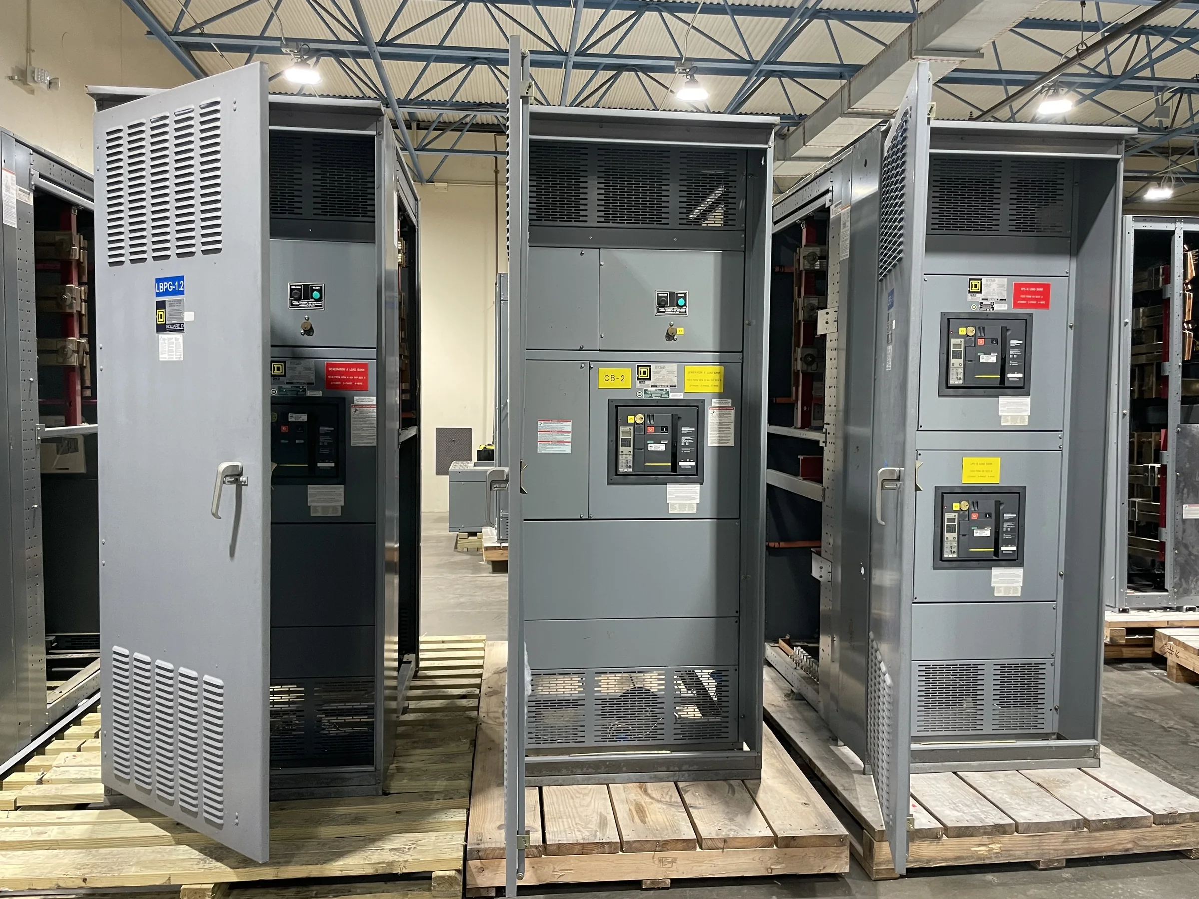
Define the Service-Entrance Duty Before Selecting an Assembly
A service-entrance switchboard sits at a consequential point in an industrial facility: it receives utility power and distributes it into the plant’s electrical system. Start with the serving utility’s requirements, available fault current, nominal voltage, phase, frequency, and the facility’s planned load—not a product name alone. Those inputs affect the main device, bus arrangement, metering provisions, interrupting ratings, and coordination with downstream equipment. Confirm whether the utility expects a particular service configuration or access arrangement, and identify who supplies and installs service conductors and metering components. A mismatch discovered after drawings are approved can require redesign, utility resubmittals, or changes to the electrical room. Final ratings, configuration, and applicable evaluations must be confirmed for the specific project.
Translate Plant Loads Into a Practical Distribution Plan
Industrial demand rarely consists of one steady block of load. Motors, process equipment, welders, compressors, variable-frequency drives, and future production lines can create different starting, operating, and expansion needs. Give the design team an accurate load schedule, including known motor data and planned additions, so the service and feeder arrangement can be reviewed as a system. Consider which processes need separate feeders, where selective coordination is required, and how the plant will isolate equipment for maintenance. These decisions affect the number and arrangement of sections, outgoing devices, and spare capacity; simply adding unused ways may not solve a future capacity constraint. A documented load basis helps engineers compare options and gives procurement a clearer scope for quote review.


Check the Room, Access Route, and Working Space
A switchboard that fits on an electrical-room drawing may still be difficult to install or maintain. Verify available wall space, ceiling height, floor openings, housekeeping pads, cable-entry direction, and the required working clearances against the project design and applicable codes. Review the complete route from receiving area to final position: door widths, turns, ramps, elevators, overhead obstructions, and the equipment’s shipping configuration can constrain delivery and placement. Also confirm whether sections must be handled separately and how they will be reassembled in the room. These checks matter because late discovery of an access restriction can force construction changes or affect the assembly layout. Provide dimensioned room plans and route details early, then reconcile them with approved submittal drawings.
Resolve Interface Details With the Utility and Plant Team
Service equipment has interfaces beyond its enclosure. Establish who is responsible for utility coordination, service-entrance conductors, grounding and bonding details, metering, protective-device settings, and downstream connections. Confirm how the switchboard ties into transformers, generators, automatic transfer equipment, or other sources, where those are part of the project. For facilities that cannot tolerate an unplanned outage, coordinate the construction sequence and planned shutdown window with operations; replacement or expansion work must be designed and scheduled around safe isolation and de-energized work. Record interface assumptions in the specifications and one-line diagram so bidders are not pricing different scopes. Clear responsibility boundaries reduce field disputes and help the commissioning team verify the intended arrangement before the plant returns to service.
Build a Submittal Package That Supports Review
A useful procurement package gives the manufacturer enough information to develop a project-specific proposal and gives reviewers a consistent basis for approval. Include the one-line diagram, electrical specifications, load information, available fault-current data, utility requirements, room and cable-entry drawings, environmental conditions, and any applicable project standards. Identify required accessories, metering functions, communication points, spare provisions, and documentation expectations rather than relying on shorthand descriptions. During submittal review, compare the proposed ratings, device types, dimensions, connection points, and interfaces against the design and utility criteria. Resolve exceptions in writing before release for manufacture. UL 891 applies to appropriately evaluated low-voltage switchboard assemblies; it is not a blanket certification for medium- or high-voltage equipment, and project-specific evaluation and labeling must be confirmed.
Plan Timing and Delivery Around the Construction Sequence
Discuss schedule and delivery requirements with the U.S. manufacturer while the design is taking shape, not after the electrical room is complete. The project schedule should account for engineering review, utility approvals, submittal revisions, manufacturing, shipping, site readiness, and installation coordination. Actual availability and timing depend on the approved configuration, components, and project conditions; obtain current project-specific information rather than treating a general estimate as a commitment. Confirm the ship-to address, receiving hours, unloading equipment, staging space, weather protection, and who can inspect and accept the shipment. Nationwide shipping supports projects across the United States, but the site team still needs a workable delivery window and a clear plan for moving equipment indoors. Aligning these details helps prevent storage, access, and sequencing problems.