Start With the Service Conditions, Not a Catalog Frame
An oil and gas facility’s service entrance switchboard has to match the utility source, the site’s load profile, and the way the facility isolates equipment for maintenance. Begin with the one-line diagram and confirm incoming voltage, phase, frequency, available fault current, main-device arrangement, metering needs, and downstream feeder requirements. These details shape bus design, protective-device selection, enclosure configuration, and space for future circuits. A switchboard that fits the nominal voltage but not the documented fault duty or utility interface can stall engineering review and complicate procurement. Share the latest utility information and load schedule when requesting a quote. The manufacturer can develop a project-specific proposal, but final ratings, component compatibility, and compliance requirements must be confirmed for the actual installation.
Account for Oilfield Loads and Operating Priorities
Production sites can combine continuous process loads with pumps, compressors, artificial-lift systems, injection equipment, and intermittent motor starts. The service entrance design should reflect how these loads operate together, not just their individual nameplate values. Ask the engineering team to identify starting methods, expected demand, power-factor correction, standby sources, and any loads that must remain available during planned isolation. Poorly coordinated assumptions can produce nuisance trips, undersized distribution paths, or an arrangement that makes routine maintenance unnecessarily disruptive. Where a facility has generators or another source, show the intended operating modes and transfer scheme on the project documents; do not assume a standard switchboard arrangement resolves source coordination. Confirm protective-device coordination and applicable arc-flash analysis with the responsible electrical engineer.


Choose Construction for the Actual Site Environment
Remote pads, gas-processing facilities, and tank-battery sites may expose electrical equipment to dust, moisture, temperature swings, vibration, or corrosive process atmospheres. Enclosure type and material should follow the documented indoor or outdoor location and the environmental conditions at the planned installation point. A shelter or electrical room can reduce direct exposure, but it does not remove the need to consider condensation, ventilation, access, and heat generated by the switchboard. Share site drawings, ambient conditions, hazardous-area boundaries, and any required coating or material expectations before the design is finalized. The equipment’s location relative to classified areas matters: an ordinary switchboard is not made suitable for a classified location simply by specifying a rugged enclosure. Verify project-specific suitability with qualified engineering review.
Resolve Layout, Access, and Installation Constraints Early
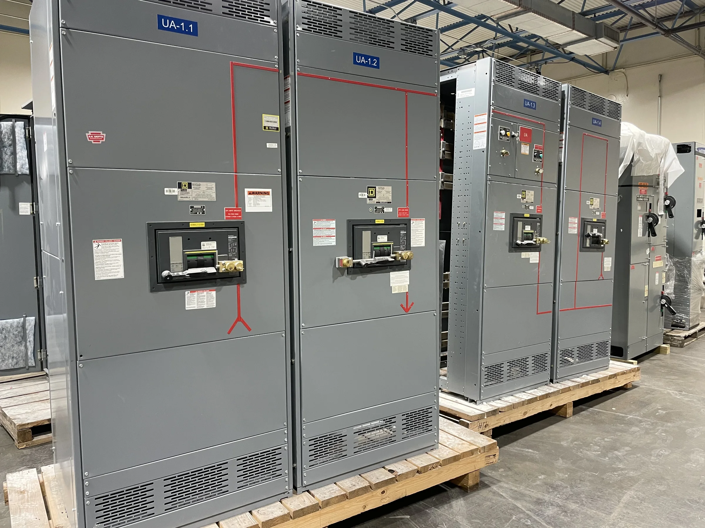
At oil and gas sites, a switchboard may need to pass through a narrow building opening, fit into a modular electrical house, or land on a prepared pad with limited maneuvering room. Confirm overall dimensions, shipping splits, door and aisle clearances, cable-entry direction, termination space, and lifting or rigging access against the site layout. These checks matter because a lineup that meets electrical requirements can still be difficult to set, anchor, or connect if the building and foundation were designed around different dimensions. Coordinate conduit routes and cable bending space with the installer, and identify whether bottom or top entry is expected. Provide foundation details and room drawings during quoting where available; final arrangement and connection provisions remain specific to the approved design.
Prepare a Quote Package That Supports Engineering Review
A useful request for quotation includes the one-line diagram, load and feeder schedules, utility service data, available fault current, equipment location, and required project standards. Add the desired metering and communications interfaces, control schematics where applicable, preferred manufacturers or approved-equal rules, and any owner documentation requirements. If the project involves replacing existing equipment, include photographs, verified dimensions, cable and conduit locations, and the existing device information; field measurements should be checked before release. Complete inputs help the U.S. manufacturer identify open technical questions before a purchase order is committed, reducing avoidable drawing revisions. State which items are mandatory and which are preferences. Ratings, component availability, UL 891 evaluation for applicable low-voltage switchboard assemblies, and other compliance details must be confirmed for the proposed equipment.
Coordinate Schedule and Delivery With Field Readiness
A short equipment lead time is most useful when it aligns with approved drawings, construction sequencing, and a site ready to receive the shipment. During procurement, confirm submittal milestones, review responsibilities, required documentation, shipping destination, receiving hours, unloading capability, and any carrier or gate-access restrictions. Remote oil and gas locations may have limited laydown space, controlled entry, unpaved approaches, or weather-sensitive access, so delivery planning should account for the actual route and site rules. Nationwide shipping can support projects across the country, but transit timing and unloading arrangements are not the same as a guaranteed installation date. Coordinate the foundation, cable pathways, and room access before dispatch. Discuss current availability and project timing directly with the manufacturer, and treat dates as subject to project-specific confirmation.