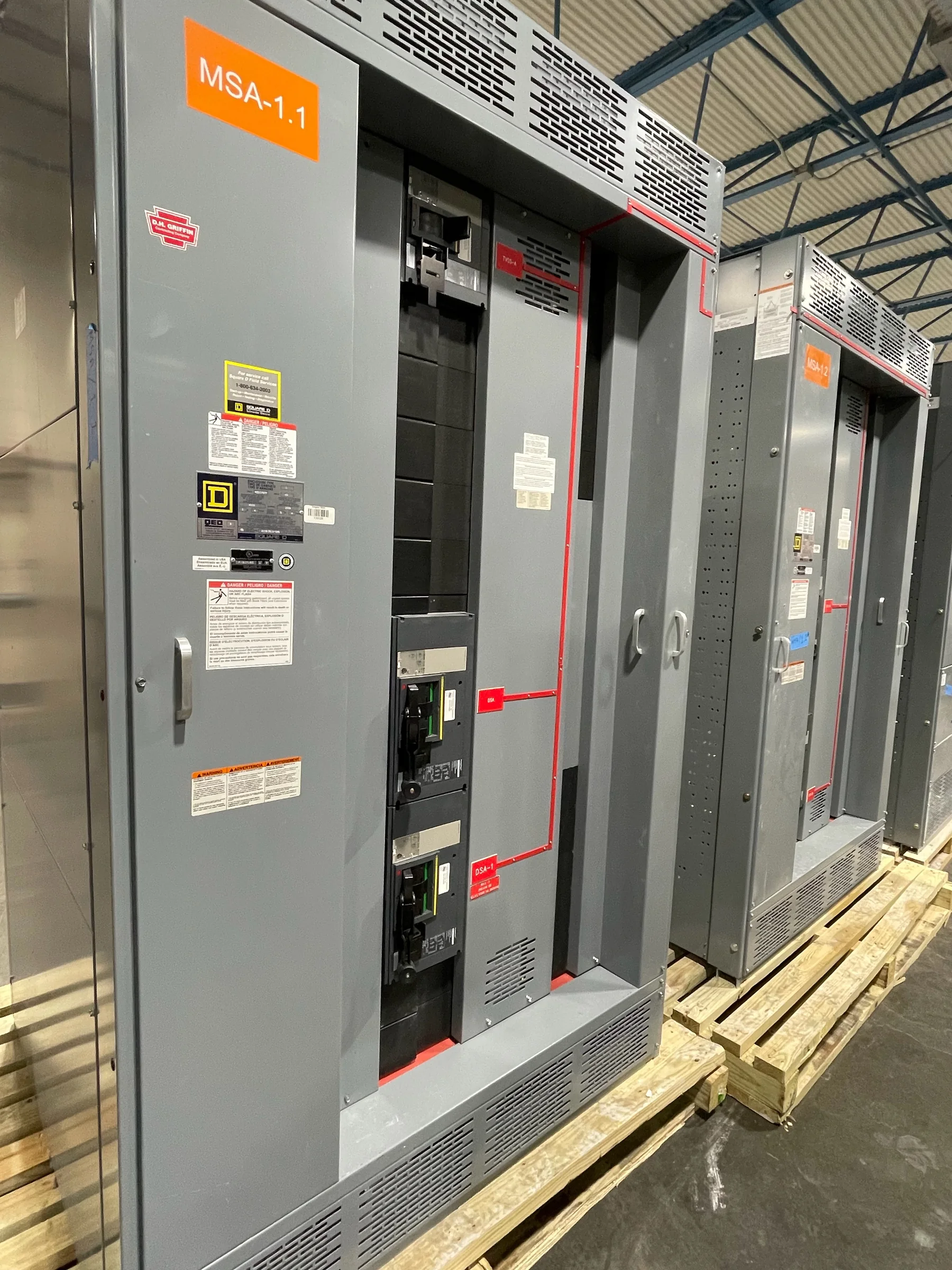
Start with the Terminal’s Load and Service Plan
A port service entrance must support more than a simple list of connected loads. Container cranes, refrigerated-container outlets, shore-power systems, workshops, warehouses, pumps, and terminal buildings can have different operating schedules and demand patterns. Before selecting a switchboard arrangement, establish the utility service characteristics, available fault current, grounding method, load schedule, and planned near-term additions. Confirm whether cranes or other large drives create starting, regeneration, harmonic, or power-quality considerations that affect the distribution design. These details help the engineering team assess bus and overcurrent-device requirements, metering, and the division of loads among sections. A load list that distinguishes existing equipment from planned expansion also reduces the risk of under-sizing the service entrance or paying for capacity the project does not need.
Coordinate Protection, Metering, and Utility Requirements
The service entrance is where utility requirements, facility protection, and operating responsibilities meet, so assumptions should be resolved before the equipment is released for manufacture. Obtain the serving utility’s current requirements for service configuration, metering location, access, disconnecting means, and approval drawings; these can vary by utility and project. The engineer of record should establish the protection approach, including device ratings, selective-coordination objectives where required, and available fault-current information. For a marine terminal, clarify how the main distribution system interfaces with separately supplied shore-power equipment or other large loads, rather than assuming those systems share the same operating or protection strategy. Documenting the boundary of supply and responsibility helps avoid drawing revisions, inspection delays, or field changes after switchboard sections arrive.


Account for Salt, Moisture, and the Enclosure Location
Salt-laden air, wind-driven rain, humidity, and airborne contaminants can affect equipment longevity, but the actual exposure depends on where the switchboard will be installed. An indoor electrical room away from the waterfront may call for different enclosure and corrosion-protection decisions than an exposed dockside installation. Identify whether the equipment is indoors or outdoors, the expected temperature and moisture conditions, washdown practices, ventilation, and proximity to salt spray. Also check room drainage, condensation control, and the possibility of water entry during storms or flooding. Those conditions inform enclosure selection and installation details; they do not replace project-specific evaluation of the environment. Include the location and exposure description in the specification so the manufacturer and design team can review appropriate construction options without assuming one enclosure suits every terminal.
Fit Sections Through the Route, Not Just the Room
A switchboard that fits on the electrical-room plan can still be impossible to deliver or position if the access route has tighter limits. Measure door openings, corridors, turning clearances, overhead obstructions, elevator or crane capacity, and the final handling path from the receiving area to the installation point. Port sites may require delivery through controlled gates, security screening, restricted work zones, or active terminal traffic routes; confirm site rules and receiving hours early. Ask the project team to review shipping splits, section dimensions, lifting provisions, and the sequence for setting and joining sections against those constraints. A coordinated logistics review can prevent a costly field workaround, but final shipping configuration and handling arrangements must be confirmed for the specific equipment and site.
Issue a Complete Package for Review and Procurement
A useful request for quotation gives the manufacturer enough project information to identify the intended scope without treating an incomplete specification as final design approval. Provide the one-line diagram, load and equipment schedules, utility service data, available fault current, grounding requirements, metering criteria, applicable project standards, and the required submittal and approval process. Identify preferred component manufacturers or American-component requirements, while allowing the engineering team to confirm availability and suitability for the specified design. State whether the project includes future sections, spare provisions, or interfaces to existing distribution equipment, and supply existing drawings when replacement work depends on them. Clear document control, review responsibilities, and revision dates help purchasing compare proposals on a consistent basis and reduce mismatches between the approved design and the ordered assembly.
Plan Schedule, Delivery, and Installation Around Operations
Terminal operations can constrain when equipment may be received, moved, and installed, particularly when a service interruption affects cargo handling, refrigeration, or shore-side support. Develop a project schedule that identifies drawing review and approval, required procurement decisions, site readiness, shutdown windows, receiving restrictions, and any coordination with the utility or other contractors. A U.S. manufacturer can discuss custom build options, American components, short lead times, and nationwide shipping, but the achievable schedule depends on the approved design, component availability, project submittals, and delivery requirements. Confirm timing and shipping arrangements for the specific order rather than relying on an assumed duration. Before installation, coordinate foundations, anchorage, working clearances, cable entry, grounding, and the planned de-energized work sequence with qualified project personnel.