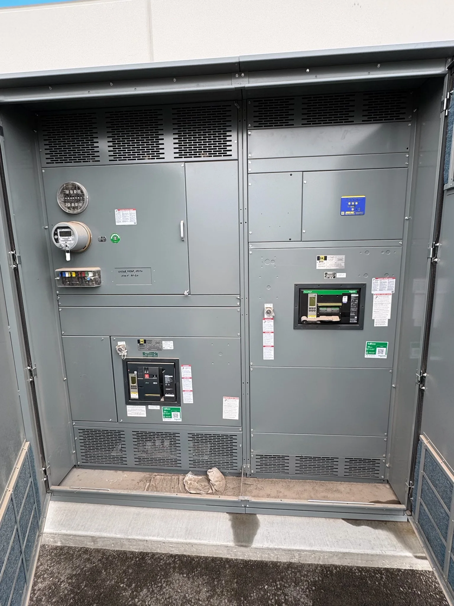
Define the Service Entrance Boundary Before Selecting Equipment
At a power plant, the service entrance switchboard must fit the actual electrical boundary between the incoming source and the facility’s distribution system. Confirm whether the incoming supply is utility power, an auxiliary transformer, or another defined source, and identify where metering, service disconnecting means, and downstream feeders belong. These choices affect compartment arrangement, bus configuration, protective-device coordination, and the information needed from the serving utility or plant electrical authority. A one-line diagram should show normal and alternate sources, operating ties, and any interlocks relevant to the proposed assembly. Clarifying ownership and operating responsibility early helps prevent a design that meets a general equipment description but cannot be approved or integrated at the intended point of connection. Ratings and applicable requirements depend on the project.
Coordinate Plant Auxiliary Power and Operating Modes
Power plants may rely on several operating states: normal generation, startup, shutdown, maintenance, and loss of an incoming source. The service entrance arrangement should be reviewed against those states rather than sized from a single snapshot of expected load. Identify which auxiliary loads must remain available, how alternate sources are connected, and whether transfers are manual or automatic. The engineer should examine available fault current, grounding method, protection settings, and coordination with upstream and downstream devices; these inputs influence equipment selection and interruption requirements. Where generator output and incoming utility power can interact, confirm the intended switching sequence and interlocking philosophy with the plant’s design team. Documenting these decisions in the one-line and control schematics gives procurement a clearer scope and helps commissioning teams verify the intended operating logic.


Translate Electrical Data into a Buildable Specification
A useful request for quotation provides more than a nominal voltage and ampere rating. Include the latest one-line diagram, load and feeder schedule, available fault-current information, grounding details, required metering, protective-device preferences, and the project’s governing specifications. Identify whether the assembly is indoors or outdoors, its physical location, cable or busway entry direction, and the space available for installation and future access. For low-voltage switchboard assemblies, specify any required evaluation or labeling criteria, including whether UL 891 applies to the proposed design; that standard is not a blanket designation for medium- or high-voltage equipment. Clearly separate mandatory requirements from preferences and approved equivalents. Complete inputs reduce assumptions, support a meaningful technical review, and make bid comparisons more useful to engineers and procurement teams.
Review Plant-Specific Environment and Room Constraints
Conditions around a generating station can affect both enclosure choices and installation planning. Review ambient temperature, humidity, dust, corrosive exposure, vibration, washdown practices, and the possibility of water intrusion at the equipment location. A switchboard placed in a controlled electrical room faces different conditions from equipment near cooling systems, fuel handling, or an exterior wall. Confirm the specified enclosure and environmental provisions against the actual exposure instead of relying on the building label alone. Room drawings should show working space, doors, overhead obstructions, cable bends, ventilation, and the route from the receiving point to the final pad or lineup location. These checks matter because an electrically suitable assembly may still be difficult to install, maintain, or safely access if the physical arrangement is not coordinated early.
Plan Submittals, Review, and Schedule Around Decisions
Project timing depends on the completeness of the design package, the number of review cycles, and the resolution of open technical questions. Establish which documents are required for approval, such as outline drawings, elevations, one-line diagrams, wiring diagrams, bills of material, and device data, and identify who is responsible for reviewing each. Confirm the submittal sequence against plant outages, construction milestones, and dependencies such as transformer, switchgear-room, or cable procurement. Requests for custom construction or American components should be discussed with the manufacturer when the scope is developed; availability and schedule are project-specific and should be confirmed in the quotation and order documents. A documented approval process gives the project team a practical basis for tracking decisions without treating an estimated production interval as a guaranteed delivery date.
Coordinate Delivery, Installation, and Turnover
A power-plant switchboard shipment has to match the site’s receiving capacity and installation sequence, not just the purchase order date. Before release, verify shipping configuration, overall dimensions and weights, unloading equipment, laydown space, access restrictions, and whether the route includes narrow doors, stairs, or overhead limits. Coordinate delivery with site safety rules, contractor availability, room readiness, and any planned outage window; nationwide shipping can be arranged, while routing and timing depend on the project. Before installation, compare the approved drawings with the delivered sections and confirm that foundations, conduits, grounding provisions, and connection points are prepared. Turnover records should capture final drawings, device information, settings responsibilities, and inspection requirements. Keeping those records aligned supports orderly commissioning and helps plant personnel maintain the distribution system over its service life.