Confirm the Service Entrance Design Basis
A service entrance switchboard has to match the utility service, the building distribution plan, and the way the facility will be operated—not just the expected load. For a Spring, Texas project, begin by documenting the serving utility’s available service arrangement, voltage, phase, frequency, and any requirements for metering, service disconnects, grounding, or utility access. Confirm whether the equipment will serve a new building, replace an existing lineup, or support a planned capacity change. The engineer should also identify calculated demand, major loads, future expansion allowances, fault-current information, and the coordination approach. These inputs affect the main device, bus arrangement, section layout, and protective-device selection. Because requirements vary by site and project, verify them with the utility and design team before requesting a firm equipment configuration.
Coordinate Utility Metering and Protection
Metering and service protection deserve early coordination because utility rules and the facility’s operating needs can shape the entire lineup. Establish who supplies and installs the metering components, where the utility requires access, and whether the service arrangement calls for provisions such as instrument transformers or a particular compartment location. Separately, the electrical engineer should define the protective-device functions and evaluate available fault current, selective coordination, and downstream equipment ratings. A proposed device cannot be assumed suitable solely because its ampere rating matches the load; interrupting and withstand considerations must align with the system study and applicable requirements. For procurement, issue the one-line diagram and control or metering notes with the request for quotation. Resolve open utility comments before release, since late changes can affect component selection, enclosure arrangement, and schedule.


Fit the Lineup to the Building and Access Route
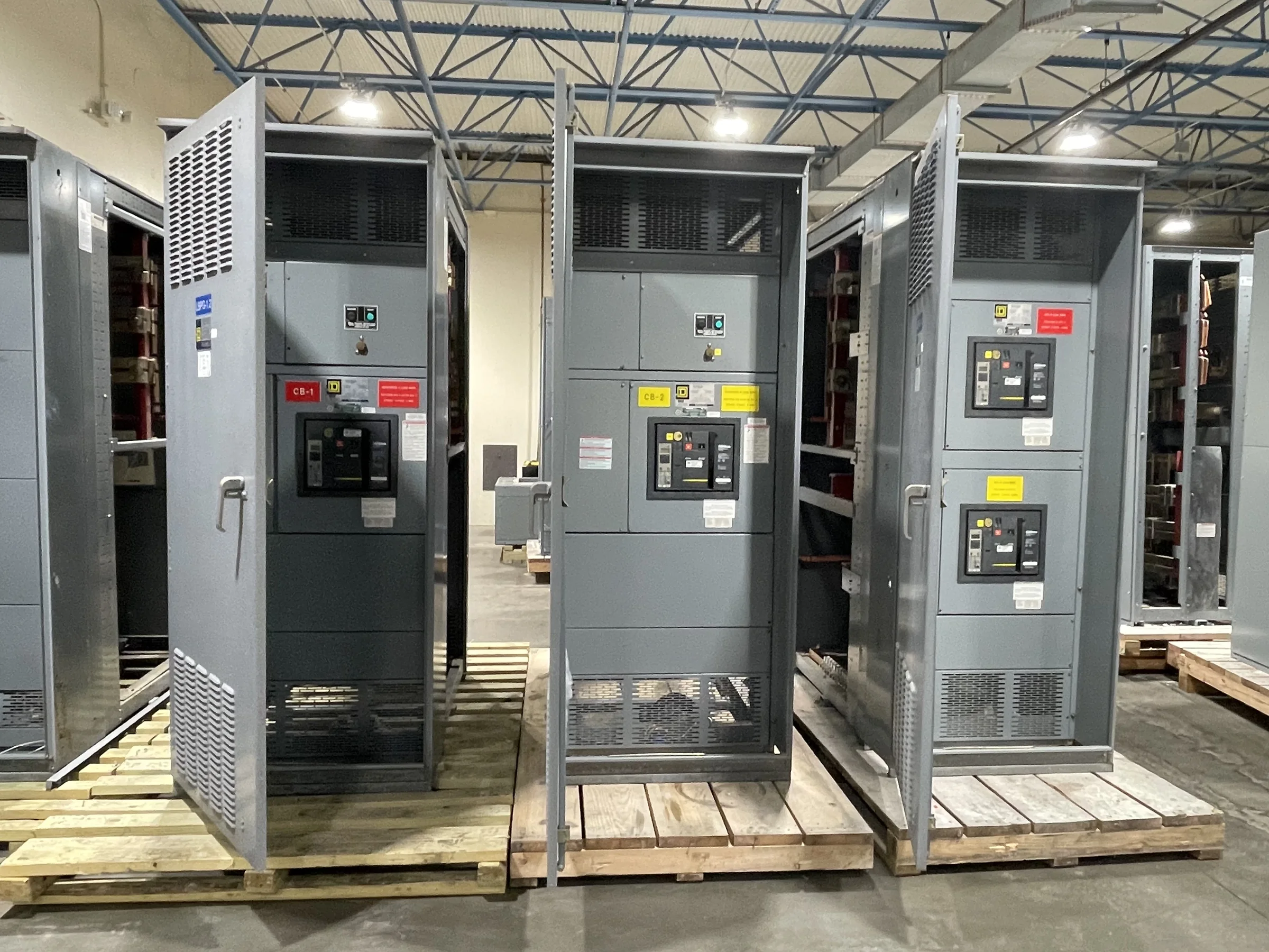
Physical fit can be as consequential as electrical fit, particularly where a Spring facility has a constrained electrical room, an existing building, or a loading area shared with other trades. Provide room dimensions, door and corridor clearances, ceiling height, housekeeping-pad details, and the intended route from the receiving point to the final location. Identify obstructions, turning limits, floor-loading concerns, and any need to move sections separately; do not assume a complete lineup can pass through the available opening. The layout should also preserve working space and access for operation and maintenance, subject to the project’s adopted codes and approved drawings. These details let the manufacturer develop a practical section arrangement and help the contractor plan rigging and installation. Confirm final dimensions and handling provisions against approved submittals before construction.
Specify Environmental and Enclosure Requirements
Spring-area projects may face heat, humidity, wind-driven rain, dust, or exposure to washdown, but the correct enclosure and equipment arrangement depend on the actual installation location. Clarify whether the switchboard will be indoors or outdoors, conditioned or unconditioned, and near corrosive chemicals, process moisture, or other contaminants. Document the expected ambient conditions and any project requirements for space heaters, ventilation, finish, or enclosure construction. Avoid choosing an enclosure designation by habit: its suitability depends on the exposure and installation, and it does not replace appropriate site drainage, clearances, or maintenance. If the equipment room is near a flood-prone area or exterior opening, coordinate elevation and water-management details with the design team. Specific environmental ratings and construction options should be confirmed for the proposed assembly and project documents.
Prepare a Complete Quote and Submittal Package
A useful quotation request gives the manufacturer enough information to identify assumptions and exceptions before equipment is released. Include the one-line diagram, load and fault-current data, utility criteria, required device functions, metering provisions, enclosure conditions, dimensions, and any control or communication requirements. State the required standards and project specifications, then ask the supplier to identify deviations rather than treating an unconfirmed feature as included. For low-voltage switchboard assemblies, UL 891 may be relevant when the proposed assembly is appropriately evaluated; it is not a blanket certification for all equipment or voltage classes. Review drawings for bus configuration, device frames and trip functions, cable access, conductor entry, and future provisions. An American manufacturer can build around project requirements and offer American components, but component availability and exact compatibility must be confirmed.
Plan Schedule, Delivery, and Replacement Work
Discuss timing and delivery while the design is still being coordinated, not after the electrical room is ready. Manufacturing duration depends on the approved configuration, component sourcing, drawing review, and project-specific requirements, so request a current schedule and confirm what milestones affect it. For delivery to Spring, coordinate the receiving date, truck access, unloading equipment, site contact, storage protection, and whether construction sequencing allows the switchboard to be placed without obstructing other work. Nationwide shipping can support the project, but the contractor should verify route and site constraints, unloading responsibility, and protection from moisture or impact after arrival. When replacing existing equipment, document outage windows, temporary-power needs, feeder identification, and the planned installation sequence. All electrical work requires appropriate de-energization and verification; retrofit scope and system compatibility must be reviewed by qualified project professionals.