Define the Service-Entrance Duty Before Selecting an Assembly
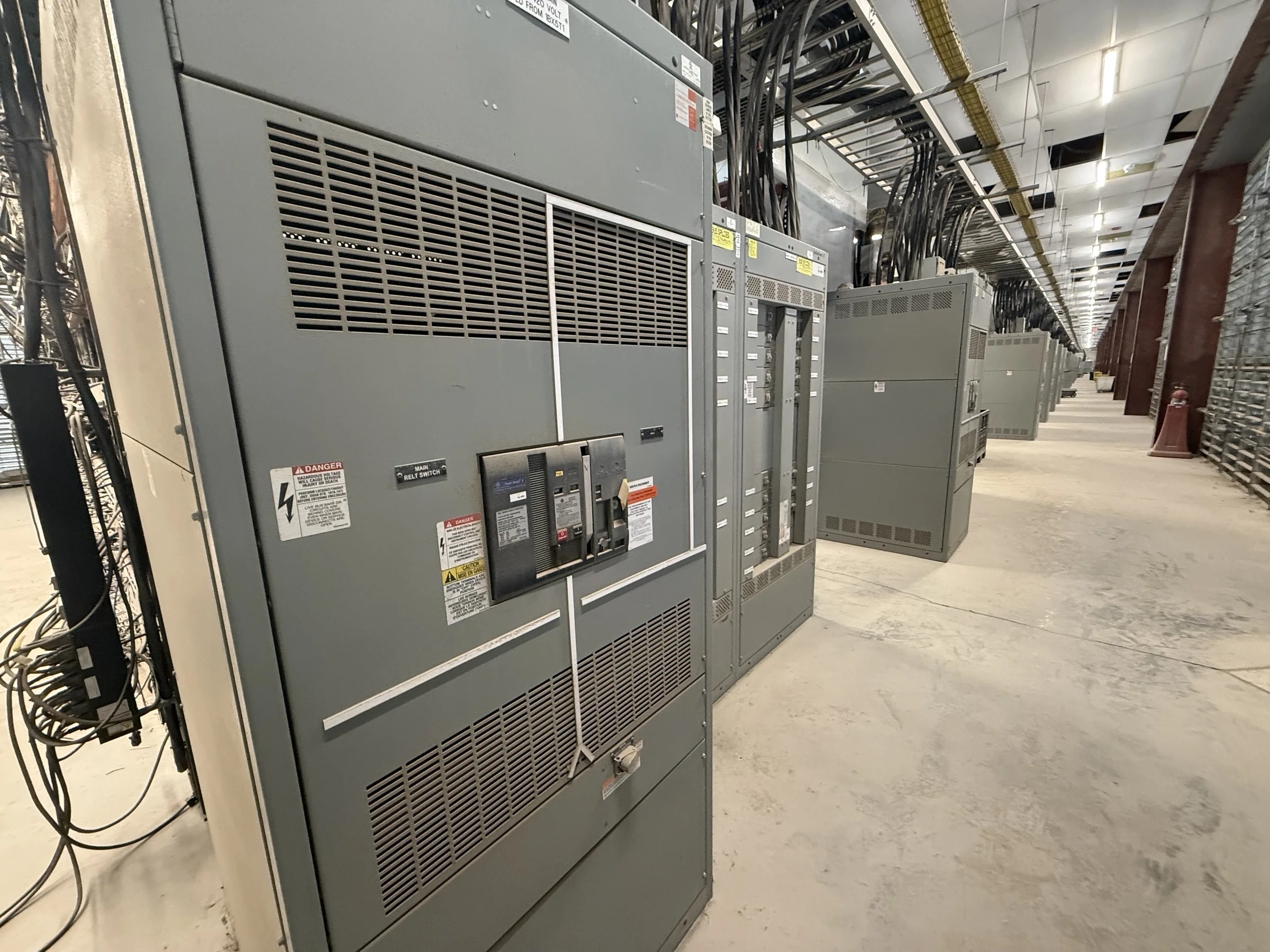
A service-entrance switchboard is part of the building’s electrical service, so its configuration must match the utility arrangement, available fault current, and downstream distribution plan—not just the connected load. For a Tomball project, coordinate early with the serving utility and the electrical engineer on service voltage, number of services, metering provisions, grounding and bonding, and the intended point of service disconnect. Those decisions affect the main section, bus arrangement, enclosure layout, and space needed for future feeders. Provide the one-line diagram, load information, and utility requirements when requesting a quote. The manufacturer can use that basis to develop a project-specific proposal; final ratings, construction, and any applicable evaluation depend on the approved design and the assembly’s intended use.
Resolve Fault-Current and Protection Requirements
Available fault current at the service is a key input because it informs equipment withstand and interrupting requirements, protective-device selection, and coordination with downstream gear. Ask the engineer or utility to document the available value and the assumptions used, including transformer data and conductor lengths where applicable; an unsupported estimate can lead to a mismatch between the design and the equipment ordered. Protection settings and selective-coordination goals also influence breaker choices and the study information needed before release. For Tomball facilities expanding existing distribution, compare proposed equipment against the current one-line and verify how the new service section will interact with existing feeders. Do not treat a familiar frame size or a similar-looking lineup as proof of electrical compatibility; confirm the complete application with the responsible design professionals.


Plan Metering, Main Devices, and Future Feeders
The service section must accommodate the metering method and main protective device required for the project, while leaving a practical path to distribution panels, motor loads, or other downstream equipment. Confirm whether the design calls for utility metering, customer metering, a particular disconnect arrangement, or provisions for future circuits. These choices can change section dimensions, access needs, bus layout, and where field connections land. A Tomball project with planned process growth may benefit from reserving defined space or capacity, but spare provisions should be identified in the drawings rather than assumed from an empty compartment. Share feeder schedules, cable or busway transition details, and any interface requirements with the quote package. The final arrangement remains subject to engineering review, component compatibility, and project-specific approvals.
Check the Electrical Room and Installation Route
A switchboard can meet its electrical requirements and still create installation problems if the room or delivery route is not checked. Measure available wall length, working space, ceiling height, door openings, turning clearances, and the route from the receiving point to the final location. In Tomball, coordinate delivery around the actual site entrance, construction access, paving condition, unloading equipment, and any restrictions imposed by an active facility or jobsite. Confirm whether the assembly must be divided into shipping sections and how those sections can be moved and rejoined under the approved installation plan. Room ventilation, environmental exposure, housekeeping pads, and conduit entry locations also affect enclosure and layout decisions. Provide dimensions and site constraints with the request so the proposed configuration can be reviewed before drawings are finalized.
Use Drawings and Submittals to Control Procurement Risk
A complete procurement package helps expose scope gaps before fabrication begins. Include the one-line diagram, load and feeder schedules, utility criteria, fault-current information, metering requirements, desired enclosure conditions, cable entry preferences, and the project’s applicable specifications. Request review drawings that clearly show the lineup arrangement, dimensions, device locations, connection points, and identified exceptions to the specification. The engineer and owner should resolve comments through the project’s approval process; a quote or preliminary layout is not a substitute for approved construction documents. For low-voltage switchboard assemblies, UL 891 may be relevant when the specific assembly is appropriately evaluated and the project requires it. It does not apply as a blanket certification for medium- or high-voltage equipment. Confirm applicable standards and labeling for the exact proposed assembly.
Coordinate Build Timing, Release, and Delivery to Tomball
Discuss schedule at the start of procurement, but base planning on the approved scope, component selection, drawing review, and current availability rather than an assumed delivery promise. A U.S. manufacturer offering custom builds, American components, and short lead times can discuss project needs and nationwide shipping; actual timing is specific to the configuration and order. Identify the required-on-site date, approval milestones, shipping destination, receiving hours, unloading responsibility, and whether delivery must be sequenced with other equipment. For a Tomball site, confirm the carrier’s route and access conditions with the project team, particularly if construction traffic, temporary roads, or limited laydown space could affect unloading. Keep the electrical contractor, engineer, utility, and facility contact aligned on handoff dates. Request replacement or retrofit equipment against verified existing conditions, not assumed interchangeability.