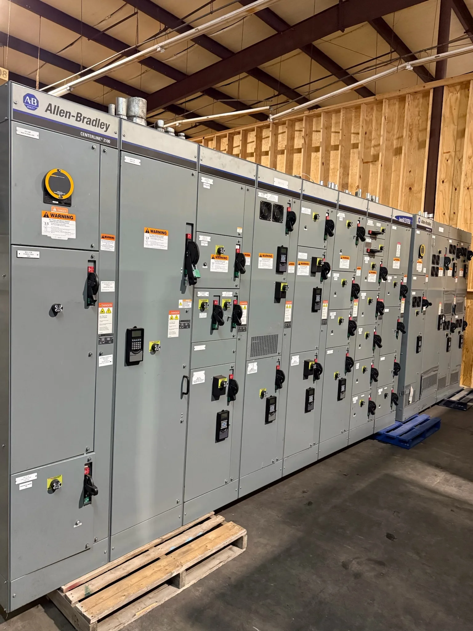
Define the Electrical Boundary Between Switchgear and UPS
Start coordination by documenting which loads the UPS will support and where its input and output connect to the distribution system. The one-line diagram should show normal and alternate sources, bypass paths, protective devices, and the point where UPS-backed circuits separate from noncritical loads. This boundary affects fault-current exposure, available maintenance isolation, and how a transfer or UPS bypass changes the source seen by downstream equipment. Identify whether the UPS is standalone or part of a larger system, and provide its operating modes and manufacturer data for engineering review. Do not assume that a switchboard or switchgear lineup can accept a proposed UPS connection without checking electrical ratings, protection, and physical arrangement. Final configuration is project-specific.
Coordinate Ratings, Protection, and Operating Modes
UPS rectifiers, inverters, static bypass paths, and maintenance bypass arrangements can present different electrical conditions to upstream and downstream devices. Give the equipment designer the UPS input and output ratings, fault-current contribution information available from its manufacturer, grounding arrangement, and transfer or bypass behavior. Engineers can then assess interrupting and withstand requirements, protective-device coordination, and the consequences of a bypass transfer or source change. A device that appears suitable during normal inverter operation may face a different condition when bypass is active. Review selectivity goals alongside applicable code, utility requirements, and the project’s protection study rather than relying on nominal load current alone. Required ratings and settings depend on the complete system and must be verified for the specific installation.


Specify Loads, Growth, and Power Quality Needs
Build the equipment schedule around actual UPS-supported loads, not only the UPS nameplate. List connected equipment, operating duty, expected simultaneous demand, future additions, and any loads with high starting current or unusual nonlinear behavior. These details help the engineering team evaluate distribution capacity, feeder arrangement, and whether the proposed architecture fits the application. Also record requirements for voltage, frequency, grounding, neutral conductors, and power-quality performance, including any sensitive process or control loads. If redundancy is required, describe the intended operating concept and what must remain energized during maintenance or a component outage; do not leave “N+1” or “critical” undefined. A clear load basis helps avoid late revisions that affect enclosure space, protective devices, conductor sizing, and procurement.
Resolve Physical Layout and Service Access Early
A coordinated electrical design must fit the room as well as the one-line diagram. Provide room plans, equipment elevations, door and corridor clearances, floor loading information, cable-entry preferences, and the locations of ducts, busway, and existing services. Confirm how switchgear, UPS cabinets, batteries, and any bypass equipment will be placed relative to one another, while preserving required working space and access for inspection and maintenance. Battery type and arrangement can affect footprint, ventilation, environmental controls, and fire-protection coordination, so these items belong in early design review. Check shipping splits and the route from the receiving point to the electrical room, including turning limits and door dimensions. Final dimensions and access requirements must be confirmed against selected equipment and governing project requirements.
Build a Complete Submittal and Procurement Package
A useful request for quotation includes the one-line diagram, load schedule, preliminary floor plan, system voltage and frequency, source information, grounding details, and project-specific performance requirements. Add the UPS manufacturer’s interface data, intended operating modes, protective-device preferences, and required communications or monitoring interfaces. Identify applicable standards and any required testing, labeling, documentation, or inspection criteria; confirm applicability for each proposed assembly rather than treating a standard as a blanket product certification. Ask the U.S. manufacturer to identify assumptions, exceptions, outstanding engineering inputs, and items supplied by others in its proposal. Reviewing those points before release helps the team compare equivalent scopes and spot interface gaps. Final equipment configuration, ratings, and compliance are subject to project review and the applicable evaluation process.
Align Factory Release, Site Readiness, and Delivery
Coordinate the equipment schedule with approved submittals, UPS selection, construction access, and the date the electrical room will be ready. Custom-built distribution equipment and short lead times may be available, but actual production timing depends on the approved configuration, component availability, and project requirements; obtain a project-specific schedule before making commitments. Resolve open interface decisions before releasing drawings for manufacture, since later changes can affect layout, protection, and shipment planning. Confirm delivery contact, receiving hours, unloading equipment, staging capacity, and whether the shipment can reach its final installation area without intermediate storage. Nationwide shipping does not remove site constraints: weather exposure, secure storage, and handling requirements should be planned with the carrier and project team. Verify delivery details and readiness milestones in writing.