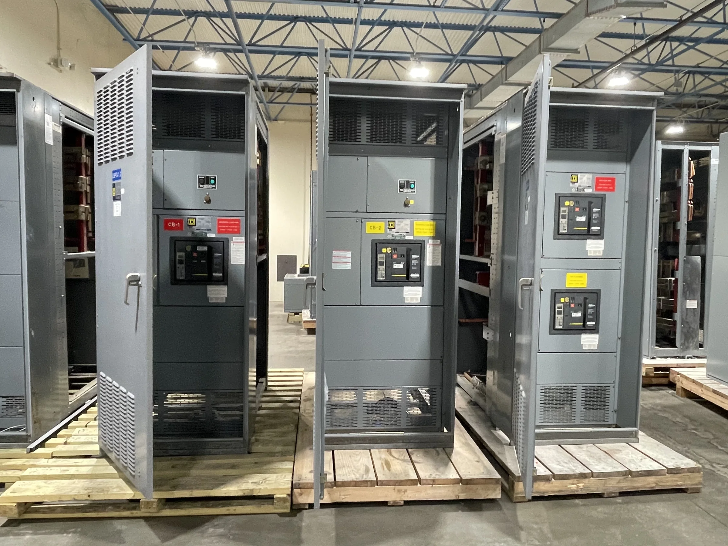
Establish the Replacement Boundary Before Selecting Equipment
A brownfield replacement begins with the existing electrical system, not a catalog model. Identify which switchgear sections, protective devices, bus connections and control circuits are in scope, then trace how they interact with upstream sources and downstream loads. Old one-lines may omit field changes, so compare them with equipment nameplates, wiring diagrams, maintenance records and a qualified field survey. Record bus arrangement, available space, cable entry points, grounding method and known fault-duty information without assuming the original design remains accurate. This boundary definition helps the project team distinguish a direct replacement from a redesign that affects coordination, capacity or operating procedures. Share confirmed information and unresolved questions with the manufacturer early; project-specific engineering must resolve compatibility before equipment is specified.
Document Interfaces That Can Prevent a Physical Fit
The enclosure footprint is only one part of fit. Measure access openings, aisle clearances, floor elevations, anchorage points and the route from receiving area to final position; a lineup that fits its room may still be impossible to move through a doorway or around a turn. Capture overhead obstructions, conduit and cable locations, existing bus duct interfaces, ventilation needs and working-space constraints for review by the responsible design professionals. Photographs and dimensioned drawings are useful, but they do not replace verified field dimensions. Note which dimensions are confirmed and which are estimates. These details help the manufacturer develop a build around actual site conditions and flag interface questions before fabrication, reducing the risk of field modifications that affect safety, schedule or acceptance.


Specify Electrical Duties and Protection as a System
Replacement equipment must suit the electrical duties it will actually encounter. The design team should confirm system voltage, frequency, source configuration, continuous load, available fault current, grounding arrangement and required protective-device functions from reliable project data. Review coordination and arc-flash studies where applicable, along with selective operation, metering, interlocking and control requirements. Do not carry forward old breaker settings or ratings simply because the existing gear has operated; system sources, transformers and connected loads may have changed. Specify relevant standards and requested evaluations clearly, then confirm applicability for the equipment type and project. UL 891 applies to appropriately evaluated low-voltage switchboard assemblies, not as a blanket certification for medium- or high-voltage equipment. Final ratings and compliance depend on the specific design and evaluation.
Plan the Cutover Around Loads and De-Energized Work
The outage plan often governs the replacement more than the equipment build. Identify critical loads, acceptable interruption windows, temporary power needs and dependencies such as process shutdowns, controls, fire protection or building systems. Assign responsibility for switching, isolation, verification of an electrically safe work condition, testing and return to service to qualified personnel under the project’s procedures. Energized work must not be treated as a shortcut to avoid outage planning. Confirm who will furnish and install temporary arrangements, and whether those arrangements require separate engineering and approvals. A sequence that separates demolition, installation, inspection and commissioning can expose schedule risks early. The manufacturer can discuss equipment interfaces and delivery coordination, but site switching, installation methods and safe-work decisions remain project-specific responsibilities.
Coordinate Submittals, Manufacturing and Delivery as One Schedule
A credible procurement schedule connects approved design information to fabrication release, site readiness and shipment—not just a requested arrival date. Identify required submittals, review cycles, drawing approval responsibilities, long-lead components and any decision dates that could affect the build. Confirm current availability and timing directly for the proposed configuration; short lead times may be offered, but no duration should be assumed until project details are reviewed. Document who approves deviations and how revisions are controlled after release. For delivery planning, establish receiving hours, unloading equipment, staging space, weather protection and the route to the electrical room. Nationwide shipping is an available offering, but freight coordination, access limitations and final delivery arrangements should be confirmed for the destination and shipment.
Prepare Installation, Testing and Closeout Records
Before the new lineup arrives, align the installation package with the approved equipment drawings and the site’s construction documents. Confirm foundations, anchorage, cable and bus connections, grounding, control wiring and required clearances against the final design; resolve discrepancies before work starts. The commissioning plan should identify inspections, connection checks, protective-device configuration, functional testing and acceptance criteria, with responsibilities assigned to qualified parties. Keep the final one-line, settings documentation, test records, operating instructions and as-built changes together for maintenance and future troubleshooting. If the project includes adjacent existing equipment, define how interfaces will be inspected and documented. A complete record set gives facility staff a reliable basis for operation and maintenance while making clear which requirements were confirmed for this specific replacement.