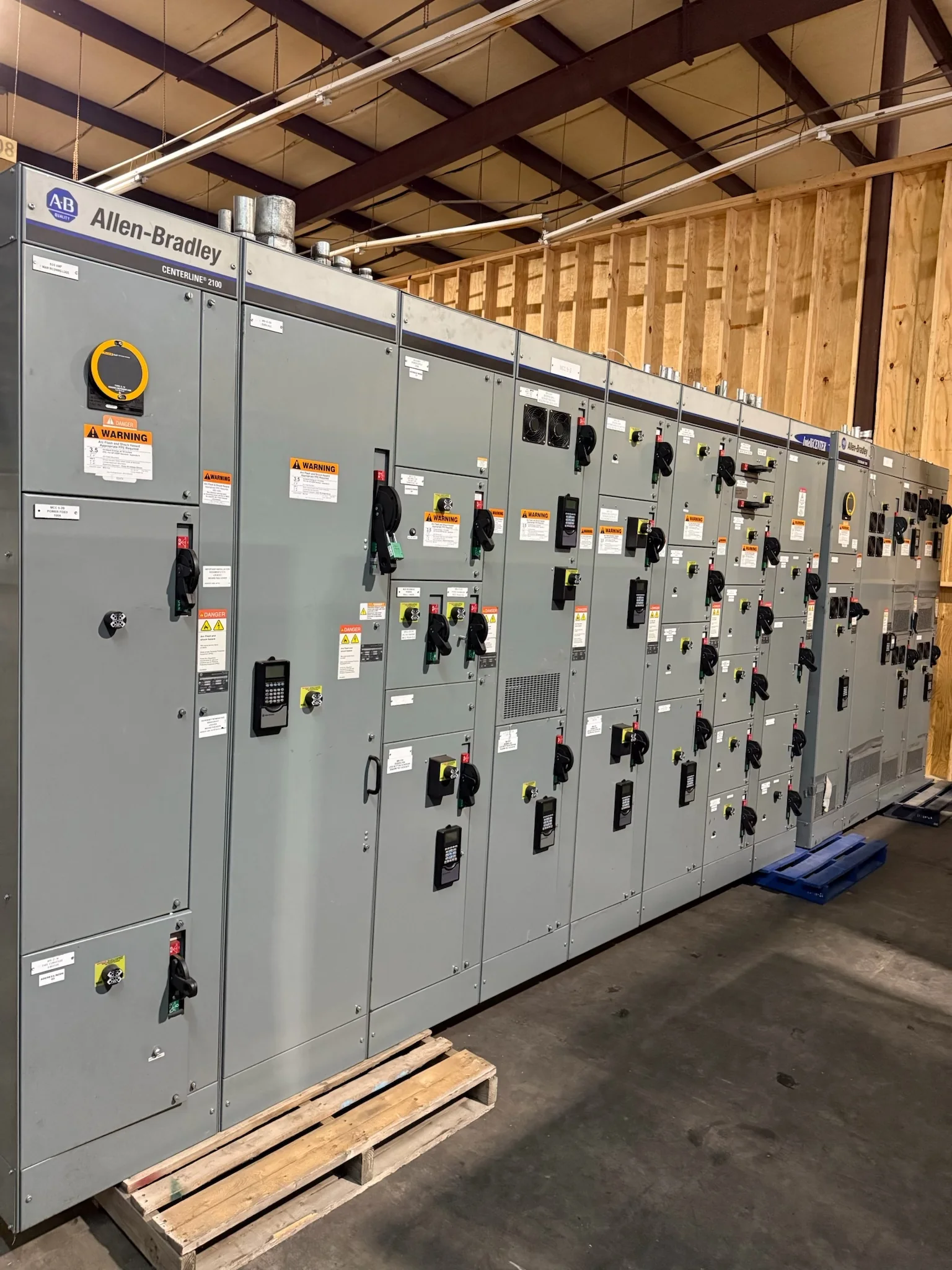
What Busbar Bracing Is Designed to Withstand
Busbar bracing supports conductors and helps limit movement when short-circuit forces act on an assembly. Those forces depend on available fault current, protective-device clearing behavior, conductor arrangement, spacing, and the construction of the complete switchboard or switchgear lineup. A bracing value viewed by itself does not establish that a proposed assembly is suitable for a particular electrical system. During planning, provide the manufacturer with the system voltage, available fault-current information, protective-device details, and the intended equipment configuration. These inputs help determine what assembly evaluation and design review are applicable. Confirm the required rating and documentation for the actual project rather than assuming that a familiar rating transfers to a different lineup, conductor layout, or installation.
Specify the Complete Electrical and Mechanical Arrangement
A useful specification describes more than bus material or a target withstand rating. Identify the main and distribution bus arrangement, incoming and outgoing connections, section lineup, equipment orientation, and any planned future provisions. Note whether the project requires copper or aluminum conductors, and state preferences without assuming that a material choice alone determines performance. Connection points and transitions between sections can affect both the electrical design and physical fit, so provide equipment schedules, one-lines, and available room drawings for review. If replacement gear must connect to existing conductors or adjacent equipment, document those interfaces and field-verified dimensions. Clear inputs give the manufacturer a basis to assess the complete configuration, identify open questions, and prepare a project-specific proposal without implying that unconfirmed compatibility is assured.


Coordinate Fault-Current Data and Protection Changes
Busbar bracing decisions are tied to the system conditions the equipment is expected to face. Request current available fault-current information from the responsible engineer or utility source, and share protective-device types and relevant trip or clearing data when available. If a transformer, generator, tie breaker, feeder, or upstream protective device is changing, revisit the study inputs; an earlier equipment selection may no longer match the revised system. Provide the latest one-line diagram and identify assumptions that remain under review. The manufacturer can use submitted information to evaluate the proposed assembly and clarify needed engineering documentation, but should not replace the project engineer’s system study or coordination responsibilities. Resolving discrepancies before release helps avoid a design based on stale or incomplete electrical conditions.
Review Drawings, Ratings, and Applicable Evaluation
Before approving production documents, compare the proposed lineup against the project one-line, equipment schedule, connection requirements, and room layout. Check that the stated assembly ratings, bus configuration, section arrangement, and protective devices correspond to the reviewed design, and flag any mismatch in writing. For low-voltage switchboard assemblies, UL 891 may be relevant when the equipment is appropriately evaluated to that standard; it is not a blanket certification for medium- or high-voltage equipment. Ask which standards and evaluation apply to the specific offered assembly and what documentation will be provided. Do not infer a label, rating, or test result from a general product description. A documented review at this stage can surface coordination issues while drawing changes are still manageable.
Plan Replacement Interfaces and Site Access
Replacement work can be constrained by existing bus connections, cable entry locations, overhead clearance, access aisles, floor conditions, and the route from the unloading point to the electrical room. Record field dimensions and photographs, noting obstructions and the space needed to position and assemble sections. Identify what existing equipment must remain, which interfaces require engineering review, and whether outages or temporary operating arrangements affect the project schedule. New equipment should be specified against verified site conditions rather than assumed to match an older lineup. Installation planning, construction sequencing, and electrical work belong with qualified project personnel; equipment must be handled and installed under applicable requirements, with de-energized work practices observed where required. Early coordination reduces the chance that a sound electrical design cannot be delivered or installed as planned.
Align Build Schedule, Shipping, and Receiving
Discuss the required in-service date, submittal review milestones, approval responsibilities, and site readiness when requesting a quote. Custom configurations, unresolved technical inputs, drawing revisions, and component availability can affect the schedule, so treat timing as project-specific and confirm it against the final scope. A U.S. manufacturer offering short lead times and nationwide shipping can discuss build and delivery coordination, but no general statement guarantees a particular completion date or transit duration. Specify the delivery location, receiving hours, unloading equipment, staging area, and restrictions on truck access. Confirm whether the shipment must arrive in a particular sequence and who will inspect it on receipt. Written agreement on these details helps procurement, engineering, and site teams coordinate without confusing a shipping estimate with installation readiness.