Map Cable Routes Before Finalizing the Switchgear
Cable entry planning starts with the route from each source and load to the proposed equipment, not just with the enclosure outline. Record whether conductors approach from above, below, or the side, and note changes in direction, elevation, and support along the way. Compare these routes with the switchgear’s available entry areas, room layout, and maintenance clearances. A route that looks direct on a single-line diagram may conflict with structural steel, ductwork, piping, or access aisles in the field. Early coordination helps the project team identify those conflicts before equipment dimensions and connections are finalized. Share the route assumptions with the manufacturer and electrical contractor so the proposed arrangement can be reviewed against the actual installation conditions.
Define Conductor and Termination Requirements
The number, size, material, insulation, and bending characteristics of incoming and outgoing conductors affect cable space and termination access. Provide the design team’s conductor schedule and identify any parallel runs, neutral conductors, grounding conductors, or control wiring that share the approach. The equipment arrangement must also account for the specified lugs or termination provisions and the working room needed to dress and secure cables. Do not assume a familiar switchgear lineup will accept a different conductor plan without review: conductor ampacity, equipment ratings, terminal suitability, and applicable code requirements must be coordinated by qualified project professionals. Confirm final requirements before approving drawings, because late changes can affect compartments, cable supports, entry locations, and the equipment configuration.


Coordinate Bottom Entry with Foundations and Floor Openings
For bottom cable entry, compare the equipment footprint with the housekeeping pad, trench, pull box, and floor-opening drawings. The opening must serve the intended cable path without interfering with structural members, embedded services, anchorage, or adjacent equipment. Confirm who is responsible for the opening dimensions and when those dimensions will be issued; construction teams may need verified equipment drawings before placing concrete or setting sleeves. A mismatch can leave cables obstructed or require disruptive field changes. Review the route for water exposure, debris, and access for pulling and securing conductors, while leaving any required sealing or firestopping to the project’s approved details. Final opening locations and dimensions are project-specific and should be checked against manufacturer drawings and site conditions before construction.
Plan Top Entry Around Room Services and Cable Support
Top entry can simplify a route from overhead tray or conduit, but the approach must be coordinated with the room’s ceiling, lighting, sprinkler piping, ventilation, and lifting or service access. Identify the intended cable-support method and the transition from tray or conduit into the equipment, including who supplies and installs each part. Check that proposed conductors can reach their terminals without violating specified bend limits or blocking access to components. Where multiple feeders converge, congestion above the lineup can complicate installation and later inspection, even when each individual route appears workable. Include overhead elevations and nearby obstructions in the layout package. The manufacturer can review the proposed equipment entry arrangement, while the project engineer and installer confirm routing, support, and code compliance for the complete installation.
Use Submittals to Resolve Entry Details Before Release
A useful submittal package ties the one-line diagram and equipment schedule to a dimensioned room plan, cable schedules, and entry-point requirements. Mark which cables enter each section, their direction of approach, and any known termination or pull-space constraints. Review manufacturer drawings for section locations, access doors, connection areas, and interfaces with the planned floor or overhead route; send comments through the project’s normal approval process. If a detail is unknown, flag it as an open item rather than treating an assumed entry location as approved. Resolving such items before fabrication can reduce drawing revisions and field rework. Procurement teams should also confirm the required review milestones, document responsibilities, and whether changes after approval could affect configuration, price, or schedule.
Connect Delivery Planning to the Installation Sequence
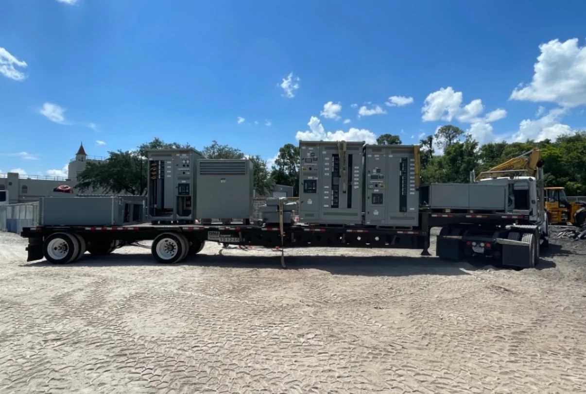
Cable entry decisions affect more than installation geometry: they can influence when the room is ready, how equipment is unloaded, and which trades need access first. Before ordering, discuss the project’s required configuration, drawing-review dates, site-readiness milestones, and delivery constraints with the U.S. manufacturer. Custom builds, American components, short lead times, and nationwide shipping are available offerings, but timing and availability depend on the project and should be confirmed rather than assumed. Verify the receiving point, unloading responsibility, route into the electrical room, storage conditions, and protection from construction damage. Keep delivery coordination aligned with the approved equipment drawings and cable-entry plan. Before conductors are installed or connected, qualified personnel must follow applicable safety procedures, including establishing and verifying a de-energized condition.