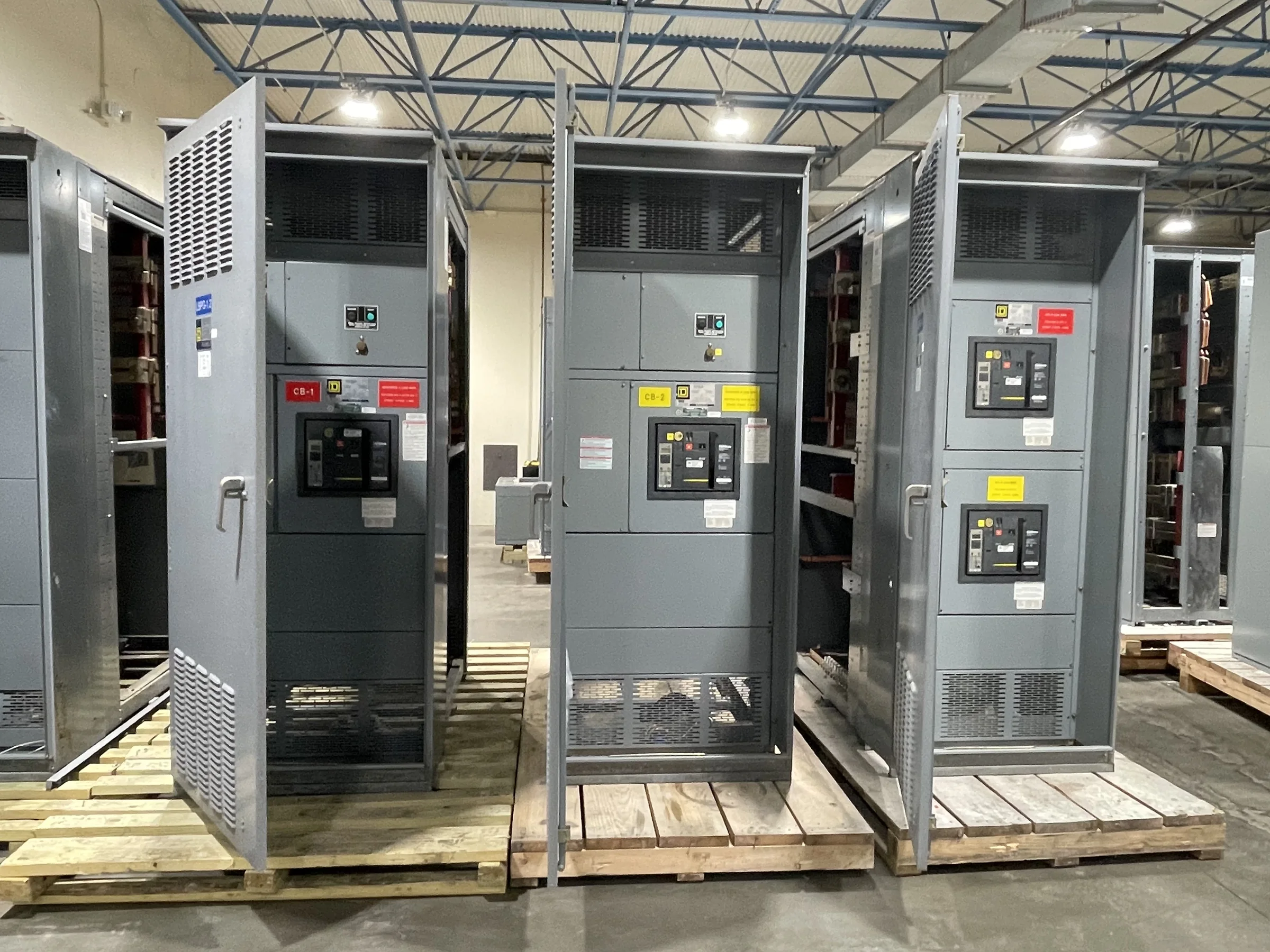
Define the Cable Entry Before Equipment Is Released
Conduit and cable termination planning should begin with the equipment layout, not after the switchgear enclosure is approved. Identify each feeder’s source and destination, conductor type, quantity, outside diameter, and intended entry direction. These details affect termination space, lug selection, bending room, barriers, and the location of cable supports. A conduit route that looks clear on a single-line diagram may collide with a bus compartment, structural steel, or a neighboring lineup section in the room. Provide current one-line diagrams, equipment elevations, cable schedules, and site routing information when requesting a quote. Confirmed project requirements help the manufacturer evaluate the proposed arrangement; final compatibility and applicable ratings remain specific to the equipment and installation.
Coordinate Conduit Openings With the Enclosure and Room
The position and size of conduit openings can influence enclosure integrity, internal clearances, and access for installation. Establish whether cables enter from above, below, or through another approved route, and show the opening locations against the switchgear outline and housekeeping pad or supporting structure. Field-cut openings made without review can expose live-part barriers, interfere with wiring, or compromise environmental protection. Provide dimensions from fixed reference points, identify the enclosure sections affected, and distinguish planned openings from later field work. Also verify that the room layout leaves space to install conduit, pull conductors, remove covers, and maintain equipment. Review proposed penetrations with the equipment supplier and responsible electrical design professional before fabrication or field modification.


Check Cable Bending, Pulling, and Termination Space
Cable ampacity alone does not establish whether a feeder can be terminated in the available switchgear space. Conductor size, insulation, quantity, bending radius, lug orientation, and the approach from the conduit all affect whether the cable can be dressed without undue strain. Crowded terminations may make inspection and maintenance difficult, while excessive pulling tension can damage insulation or connections. Submit conductor data and the intended routing so the equipment arrangement and termination provisions can be reviewed together. Confirm applicable code requirements and manufacturer instructions with the project’s qualified electrical professionals; do not assume a cable will fit because a lug is available. Allow room for installation tools, phasing checks, and safe access after the conductors are landed.
Specify Lugs, Grounding, and Conductor Materials
A complete termination schedule should identify conductor material, size, quantity per phase, insulation details, and whether conductors are solid or stranded where relevant to the selected connection hardware. Specify lug requirements, including any project constraints on compression or mechanical connections, rather than treating the lug as an interchangeable accessory. Grounding conductors and bonding paths also need clear coordination with the equipment design and site grounding system. Aluminum and copper conductors can call for different connector considerations, and project documents should make the intended material unambiguous. The manufacturer can use these inputs to assess a proposed configuration, but final compatibility depends on the actual assembly, terminal provisions, and applicable requirements. Resolve substitutions before procurement to avoid costly field rework.
Align Drawings, Submittals, and Change Control
Termination details should remain consistent across the one-line diagram, cable schedule, conduit plan, equipment elevations, and installation specifications. Conflicting feeder names or conductor quantities can delay drawing review and lead to incorrect conduit placement or material orders. Assign a revision date to each document and identify open design decisions, such as spare conduits, future feeders, or alternate entry locations. During submittal review, check that the proposed equipment arrangement reflects the approved routing and termination data—not simply the overall lineup dimensions. Route changes after release should be documented and reviewed before anyone cuts an opening or orders cables. Clear revision control gives procurement, engineering, the manufacturer, and the installing contractor a shared basis for resolving scope and compatibility questions.
Plan Site Readiness, Schedule, and Delivery
A workable delivery plan accounts for more than the switchgear ship date. Confirm access routes, door and ceiling clearances, unloading equipment, receiving hours, storage conditions, and the sequence for moving lineup sections into the electrical room. Conduit stub-ups and cable pulls should be coordinated with the approved equipment layout, but site work must not assume an unverified opening or termination arrangement. Share the requested delivery window, destination constraints, and any phased installation needs when discussing timing with the U.S. manufacturer. Custom builds, component choices, drawing approvals, and project scope can affect availability; confirm schedule and shipping details for the specific order rather than relying on a general estimate. Before installation or termination, follow project safety procedures and ensure electrical work is performed de-energized by qualified personnel.