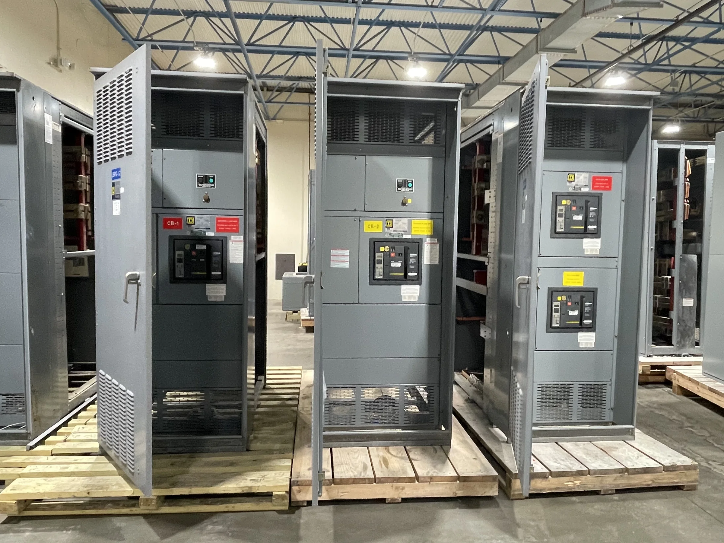
Define What the Control Power Must Operate
Start the control-power specification with the devices that depend on it, not a guessed voltage or transformer size. List breakers, protective relays, meters, indication, communications equipment, trip and close circuits, alarms, and any control interfaces supplied by other packages. Note which loads must operate together, which are intermittent, and which must remain available during a source transfer or loss of normal power. This inventory helps the engineer distinguish continuous demand from short-duration operating demand and identify loads that could otherwise be omitted from the calculation. It also gives the manufacturer a practical basis for reviewing the proposed arrangement. Confirm interface responsibilities with the switchgear, generator, UPS, and building-control teams before freezing drawings; mismatched assumptions can leave a device without usable control power.
Choose the Source and Define Its Failure Behavior
Decide whether control power will come from an external station battery, an uninterruptible power supply, a control-power transformer, or a project-specific combination. The right choice depends on system design, required operating sequence, available sources, and the consequences of losing control power—not on a universal preference. Document what remains operable after loss of normal AC, whether automatic transfer is required, and how restoration should behave. For battery-backed systems, coordinate the battery and charger scope, monitoring, autonomy criteria, and distribution boundaries with the responsible engineer. For transformer-fed arrangements, clarify the source circuit and protection. These details matter because the control source affects wiring, space, interfaces, testing, and procurement; a late change can alter both switchgear drawings and equipment furnished by other vendors.


Coordinate Voltage, Protection, and Circuit Separation
Show the required control-circuit voltages and identify every point where power is transformed, rectified, distributed, or shared. Verify device input requirements against approved manufacturer data, including relays, breaker operators, communications hardware, and accessories; nominal labels alone may not establish acceptable operating conditions. Ask the design team to define overcurrent protection, disconnecting means, grounding, and conductor identification for each circuit under the applicable project criteria and codes. Separate circuits where the design requires independent protection or fault isolation, and clarify whether different sources may be present in the same assembly. This planning is important because a fault or maintenance action on one branch should not unintentionally disable unrelated functions. Resolve these decisions on schematics and wiring diagrams before fabrication rather than relying on field interpretation.
Make Drawings and Scope Boundaries Procurement-Ready
A useful request for quotation includes the one-line diagram, equipment schedule, control schematics, operating sequence, site conditions, and the required submittal and review milestones. Mark which party supplies upstream sources, batteries, chargers, UPS equipment, interposing relays, field wiring, and network connections. Identify signals that cross the switchgear boundary and state their intended function, voltage, and termination responsibility. Include preferred component standards or manufacturers where they are project requirements, while allowing the manufacturer to identify exceptions or compatibility questions for review. Clear scope prevents gaps such as an unassigned control feed or duplicated accessory. It also makes bids easier to compare: procurement can distinguish included equipment from assumptions, and engineering can evaluate deviations before they become approved-submittal or construction issues.
Plan the Physical Layout and Installation Interfaces
Control-power equipment needs maintainable space, clear wire routes, and practical access alongside the switchgear’s primary compartments. Review the proposed location for cable entry, battery or UPS placement, ventilation, environmental conditions, housekeeping pads, working clearances, and access for replacement components. Confirm routing between the control source and the assembly, including conduit or cable-tray ownership and any separation required by the design. At the site, check doorways, corridor turns, elevator or rigging limits, receiving access, and the final path to the installation area before approving shipping arrangements. These constraints matter because a design that fits electrically can still be difficult to install or service. Provide current room plans and delivery restrictions with the inquiry; equipment configuration, shipping sections, and handling plans remain project-specific.
Align Review, Testing, and Delivery with the Schedule
Build control-power decisions into the project schedule early enough for engineering review, submittal approval, component coordination, and any required inspection or test planning. Identify who reviews schematics, who approves protection and operating sequences, and how revisions will be documented. Define requested factory checks and site acceptance responsibilities in the procurement documents; test scope and available procedures depend on the specified assembly and project requirements. Before release, reconcile approved drawings with interface lists, field-device data, and the latest one-line diagram. Share the required delivery window, receiving hours, unloading resources, and storage conditions with the U.S. manufacturer, then confirm availability and shipping details for the actual order rather than assuming a standard lead time. Early coordination reduces avoidable redesign, delivery conflicts, and commissioning questions.